A small pumping station hangs off one 4-20 mA loop. Below 3.6 mA is a broken wire or a dead transmitter, above 21 mA is a shorted loop, and both have to hand the wet well to the high-high float rather than let the pumps run on a number nobody trusts. Get that signal honest and the rest is arithmetic: lead pump in at 2.80 m and out at 1.20 m, lag in at 3.60 m, high level alarm at 4.20 m. This walkthrough covers the parts of a small works that cause the most call-outs: wet well level, lead and lag pump alternation, chlorine dosing, and remote sites on cellular Modbus.
The example is a pumping station with two submersible pumps and a clean water contact tank with residual control.
The site
| Item | This example |
|---|---|
| Controller | 1756-L83E, firmware 33.011, Studio 5000 v33 |
| Level | Submersible piezoresistive transmitter, 4-20 mA, 0 to 5 m, vented cable |
| Analog input | 1756-IF8, 4-20 mA mode, raw counts 3277 to 16384 |
| Pumps | Two 11 kW submersibles on PowerFlex 525 drives, EtherNet/IP |
| Backup level | Two float switches, high and high-high, wired to a 1756-IB16 |
| Dosing | Sodium hypochlorite metering pump, 4-20 mA speed, residual analyser 0 to 2 mg/l |
| Panel | 316 stainless NEMA 4X, gland plate at the bottom, no holes in the top |
| Remote sites | Cellular router, Modbus TCP over VPN, 30 second poll |
Step 1: Get the level signal honest
Everything downstream depends on one 4-20 mA loop.
- Scale the raw count in engineering units and nothing else. For the 1756-IF8 in 4-20 mA mode, 3277 counts is 4 mA and 16384 counts is 20 mA, so the span is 13107 counts across 0 to 5 m.
- Lower the level in the wet well with the pumps in hand and check the reading against a dip tape at two points. Not one. Two points catch a span error that a single point hides.
- Filter, do not smooth to death. A 3 to 5 second filter takes out the surface chop. A 60 second filter makes the pumps hunt because the control sees the level too late.
- Alarm on the signal itself. Below 3.6 mA is a broken wire or a dead transmitter, above 21 mA is a shorted loop. Both should raise a fault and force the floats to take over.
- Keep the float switches in the logic. A high-high float that starts a pump regardless of the analog reading has saved more sites from flooding than any diagnostic.
(* LiftStation, 500 ms periodic task *)
Level_m := (Level_Raw - 3277.0) * (5.0 / 13107.0);

Level_Fault := (Level_Raw < 2949) OR (Level_Raw > 17203);

IF Level_Fault THEN
    Lead_Call := HH_Float;          (* floats take over *)
    Lag_Call  := 0;
END_IF;
Step 2: Set the start and stop levels with real deadband
An on/off level control needs a gap between start and stop that reflects how much water you want to move per cycle.
- Lead pump starts at 2.80 m, stops at 1.20 m. That is 1.6 m of drawdown.
- Lag pump starts at 3.60 m, stops at 2.00 m.
- High level alarm at 4.20 m, high-high float above that.
Too small a deadband gives you short cycling, and a submersible motor has a maximum starts per hour on its nameplate. Count the starts in the PLC with a CTU and alarm when the hourly total exceeds the nameplate figure. That single counter finds a failing non-return valve long before anyone notices the pump is doing nothing.
Step 3: Alternate the pumps properly
Alternation is not just a toggle. It has to respect availability, or the logic will keep handing the lead to a pump that is tripped.
(* start and stop with deadband *)
IF Level_m >= 2.80 THEN Lead_Call := 1; END_IF;
IF Level_m <= 1.20 THEN Lead_Call := 0; END_IF;
IF Level_m >= 3.60 THEN Lag_Call  := 1; END_IF;
IF Level_m <= 2.00 THEN Lag_Call  := 0; END_IF;

(* swap the lead on every new call, so wear is shared *)
IF Lead_Call AND NOT Lead_Call_Last THEN
    Lead_Is_P1 := NOT Lead_Is_P1;
END_IF;
Lead_Call_Last := Lead_Call;

(* an unavailable pump never holds the lead *)
IF NOT P1_Available THEN Lead_Is_P1 := 0; END_IF;
IF NOT P2_Available THEN Lead_Is_P1 := 1; END_IF;

P1_Run := P1_Available AND ((Lead_Is_P1 AND Lead_Call)
                        OR (NOT Lead_Is_P1 AND Lag_Call));
P2_Run := P2_Available AND ((NOT Lead_Is_P1 AND Lead_Call)
                        OR (Lead_Is_P1 AND Lag_Call));
P1_Available is the one to get right. It should mean drive healthy, not in local, thermal contact closed, and moisture probe clear. Feed it from the drive status word rather than a contactor auxiliary, and the HMI can then tell an operator why a pump is out.
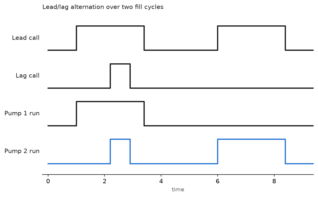
Some sites prefer to alternate on run hours instead of on every start. Run a RTO per pump, and give the lead to whichever has fewer hours when a new call starts. Either is defensible. Alternating every start is simpler and keeps the hours within a few percent on a site with similar duty.
Step 4: Dose chlorine without chasing your tail
Residual control is a long dead time problem. The analyser sees what the dosing pump did several minutes ago, at the contact tank, not at the injection point.
- Pace the dose on flow first. Dose rate equals flow times target dose, worked out in the PLC from the flow meter. This gets you most of the way with no feedback at all.
- Trim that feed-forward with a slow PID on the residual. Small proportional gain, long integral time in the tens of minutes, derivative off.
- Clamp the trim. Plus or minus 20 percent of the flow-paced dose is plenty. A trim with no clamp will drive the pump to a limit the first time the analyser fouls.
- Freeze the integral when the dosing pump is at a limit or the flow is below the minimum. Windup on a dosing loop is how you end up over-chlorinating for an hour after a low flow period.
- Alarm on the analyser being flat. A residual that has not moved by more than 0.01 mg/l in two hours while flow is changing means the sample line is blocked, not that the control is perfect.
The loop setup and bump testing is the same as any other, and the detail is in PLC PID control in Studio 5000 with the signal path covered in PLC PID control automation.
Step 5: Assume the remote site goes quiet
A borehole or a small pumping station on a cellular link is not a remote I/O rack. An oil and gas wellpad sits at the same end of the same problem, and the poll budget and shutdown latching for one are worked out in wellhead ESD logic and RTU polling.
- Poll slowly. 30 seconds is enough for a level and a run status. One second polling costs data, drains the allowance and tells you nothing extra about a tank that fills over four hours.
- Put the control at the remote site. The remote PLC decides when its own pump starts, using its own level. The central system asks for a target and reads back status. A site that only runs while the radio is up will fail on the worst night of the year.
- Stamp the data. Every value the central system receives needs an age. If the last good read is older than three poll intervals, show the value greyed with a comms alarm instead of a stale number that looks live.
- Map the Modbus registers once and write the map down in the project. Holding register 40001 for level in tenths of a metre, 40002 for flow, coils for pump status. Keep that table in the ACD description fields as well as in the drawing.
- Retry sensibly. A message instruction that retries every scan after a timeout will hold the connection open and block everything else. Retry, back off, alarm.
Field notes
The vent tube that got wet. A submersible level transmitter reads gauge pressure and vents to atmosphere through a tube in the cable. The terminal box on this site had no breather desiccant and filled with condensation. The level read 0.4 m high on cold mornings and normal by lunchtime, so the pumps started late and the well nearly overflowed twice. A dip tape check at 7am found it in ten minutes. Every submersible transmitter needs a dry, vented termination.
Both pumps starting after a power dip. A brief supply dip reset the controller. On the first scan, both Lead_Call and Lag_Call evaluated true because the well had filled during the outage, and both 11 kW pumps started in the same scan on a generator supply. It tripped. A staggered start, with the lag pump inhibited for 10 seconds after a restart, fixed it. Use the first scan bit for this, as in PLC first scan bit.
The pump that was never really available. Pump 2 had a failed moisture probe and had been locked out at the drive keypad for months. The PLC did not know, because availability came from a contactor auxiliary that was still closed. Alternation kept handing it the lead, the lead call did nothing, and the level climbed until the lag started. Everyone thought the level control was badly tuned. It was a missing status bit.
Chlorine analyser fouled, loop wound up. The sample line partly blocked over a weekend and the residual reading fell steadily. The trim PID, with no clamp and no windup protection, drove the dosing pump to full. Monday morning had a residual well over target and a lot of paperwork. The fix was the clamp in step 4, plus an alarm on a flatlined analyser. Setting analog alarm limits properly is covered in PLC analog alarm (ALMA).
Frequently asked questions
Ultrasonic or submersible for wet well level?
Submersible transmitters are unaffected by foam and fat layers but sit in the sewage and need a vented termination. Ultrasonic keeps the instrument out of the water but loses the echo on foam and gets confused by grease on the face. On raw sewage I use submersible with float backup. On clean water either works.
Do I need PID for level?
Not for a wet well with fixed speed pumps. On/off with deadband is correct and simpler. Use PID where a variable speed pump holds a level constant, for example a filter inlet or a balance tank feeding a downstream process.
How do I stop pumps short cycling?
Widen the deadband first. If you cannot, because the well is small, look at the non-return valve and whether water is coming back. Count starts per hour and alarm on it.
What should the panel be made of?
316 stainless in a wet or chlorine area, with a gland plate at the bottom. Never drill the top of an outdoor enclosure. Sunlight also heats a stainless panel enough to matter, so check the drive derating before you close the door on it.
How do I get historical data off a remote site?
Buffer at the remote PLC and upload when the link is up, rather than relying on the SCADA to poll everything continuously. The trending side is in PLC trend chart settings and monitoring.
Next step
Get the alarms right before you get clever with the control, because an unattended site is only as good as the alarm that wakes someone up. PLC analog alarm state diagrams covers the states an analog alarm moves through, and what is SCADA sets out how those alarms reach the person on call.