Tank level reading 3276.7 percent on the operator faceplate is what an unsigned register map produces, and a flow number off by a factor of ten is the same fault at a different address. A skid that arrives with its own controller and then has to answer to a DCS needs three things settled before anyone writes code: one writer per register, a heartbeat running in both directions, and a written owner for every alarm. Get those right and commissioning takes two days. Get them wrong and the argument about the flow reading lasts a month.
The walkthrough below uses a DeltaV EIOC talking Modbus TCP to a 5069-L306ER. The same sequence works for Experion PKS and for PCS 7.
What you need
| Item | Notes |
|---|---|
| Skid controller | 5069-L306ER CompactLogix here. An S7-1500 or a Modicon M580 changes only the tag syntax |
| DCS interface | DeltaV EIOC for Modbus TCP and EtherNet/IP, Experion C300 with a Modbus TCP channel, or a PCS 7 AS 410 with the skid coupled as a PROFINET I-Device |
| Modbus server on the PLC side | Rockwell’s Modbus TCP sample code over the socket object, or a standalone ProSoft DIN-rail gateway. The 1769-bus MVI69E-MBTCP card does not fit a 5069 rack |
| Signal list | A spreadsheet both parties sign. This is the actual deliverable |
| Network drop | One VLAN for the skid, one firewall rule, no shared office switch |
| Test master | Modbus Poll or qModMaster on a laptop, for proving the map before the DCS is pointed at it |
Decide what each system is for
A DCS is one engineered database that happens to have controllers attached. Alarms, historian points, graphics and control modules come from the same configuration, so a change to a PID block reaches the operator screen without anyone drawing anything. It is built for continuous process, with a control room that manages alarm load under ISA-18.2.
A PLC is one fast machine. Millisecond scan, interlocks, sequences, motion. Tags belong to the program; the HMI is a separate project someone keeps in step.
Neither replaces the other on a process plant. The DCS owns the loop that spans three vessels. The skid PLC owns the twelve-step clean-in-place sequence that nobody in the control room wants to see the inside of. Where the operator layer sits is covered in SCADA systems and their integration with PLC.
Pick the link protocol
| Option | Use it when | Watch out for |
|---|---|---|
| Modbus TCP | The DCS has a Modbus channel and the signal count is under a few hundred | No data types, no timestamps, word order fights |
| EtherNet/IP | Rockwell skid and a DCS interface card that speaks CIP, such as the DeltaV EIOC | The DCS becomes an I/O scanner, so the RPI is now your problem |
| OPC UA | You want named tags, data types and status codes, and 250 ms updates are fine | Certificate exchange, and one more PC to patch |
| PROFINET I-Device | Siemens skid into PCS 7 | GSDML imported on both sides, and the I/O areas must match byte for byte |
| Hardwired | Safety permissives, emergency stop, run-ready | Terminal count, but it works when the network does not |
I still hardwire the emergency stop chain and the skid healthy contact even when the data link carries the same information. A dry contact does not need a certificate renewed. Protocol background is in PLC communication protocols for SCADA, and the UA side is in OPC for PLC integration.
Build the register map before you write a line of code
The map is the contract. Write it first, circulate it, freeze it, then code against it. Leave gaps so the vendor can add points later without renumbering everything.
| Modbus address | FC | Logix tag | Type | Units | Written by |
|---|---|---|---|---|---|
| 40001 | 3 | Skid.StatusWord | INT bitfield | bits 0 to 15 | PLC |
| 40002 | 3 | Skid.SeqStep | INT | step 0 to 24 | PLC |
| 40003, 40004 | 3 | Skid.Flow | DINT over 2 registers | m3/h times 100 | PLC |
| 40005, 40006 | 3 | Skid.TankLevel | DINT over 2 registers | percent times 100 | PLC |
| 40007 | 3 | Skid.AlarmWord1 | INT bitfield | first-out bits | PLC |
| 40010 | 3 | Skid.HeartbeatOut | INT | rolls 0 to 999 | PLC |
| 40051 | 16 | DCS.CmdCode | INT | 1 start, 2 stop, 3 CIP | DCS |
| 40052 | 16 | DCS.CmdRequest | INT | 0 or 1 | DCS |
| 40053, 40054 | 16 | DCS.FlowSetpoint | DINT over 2 registers | m3/h times 100 | DCS |
| 40060 | 16 | DCS.HeartbeatIn | INT | rolls 0 to 999 | DCS |
Two rules save arguments later. One writer per register, always. And no 32 bit floats on the wire if you can avoid them: send a scaled integer and divide on the receiving side, so a word order mismatch produces an obviously wrong number instead of a plausible one.
Add a heartbeat in both directions
A TCP socket can sit open and happy while the controller behind it sits in program mode. The only honest test is a number that keeps changing.
// Skid PLC, 500 ms periodic task
Skid.HeartbeatOut := (Skid.HeartbeatOut + 1) MOD 1000;

// Watchdog on the value the DCS writes
IF DCS.HeartbeatIn <> HB_Last THEN
    HB_Last      := DCS.HeartbeatIn;
    HB_Timer.PRE := 3000;          // 3 s, six missed updates
    HB_Timer.TT  := 0;
    HB_Timer.DN  := 0;
END_IF;

TONR(HB_Timer);
DCS_Comms_OK := NOT HB_Timer.DN;

IF NOT DCS_Comms_OK THEN
    Skid.CmdAccepted := 0;
    Skid.HoldRequest := 1;         // hold in place, do not slam shut
END_IF;
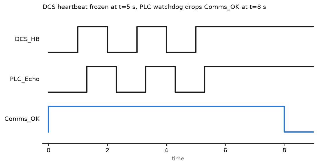
Pick the failure action with the process engineer, not on your own. On a dosing skid, holding the last valid setpoint for 30 seconds and then ramping to zero is usually right. On a burner it is not.
Send engineering units and say so on the map
Raw counts crossing a system boundary are how a level ends up reading 3276.7 percent. Scale in the PLC, where the instrument range lives, and write the range into the signal list next to the register. If both sides scale, one gets changed later without the other knowing.
Time works the same way. Modbus carries no timestamps, so sequence-of-events data needs its own first-out word plus a millisecond counter. Otherwise you accept the timestamp from the moment the DCS polled, which is fine for a tank level and useless for a trip investigation.
Settle alarm ownership in writing
The rule that has never failed me is that the system which can act on the alarm owns it.
- Process alarms with an operator response go in the DCS, configured as DCS alarms with DCS priorities. The PLC sends the condition as a bit, nothing more.
- Machine faults with no control room response stay on the skid HMI and get summarised upward as one grouped skid fault bit plus a fault code register.
- Diagnostic and maintenance alarms do not reach the control room at all.
Send the condition, not the alarm state. Acknowledged and shelved flags stay inside the DCS; two alarm state machines pointed at the same condition drift apart within a week. Alarm logic on the PLC side is in PLC alarm instructions.
Handshake every command from the DCS
Commands need a confirmed exchange, not a pulsed bit and a hope.
- DCS writes
CmdCode, then setsCmdRequestto 1. - PLC reads the code on the rising edge of
CmdRequest, checks it against the current sequence step, and setsCmdAcceptedorCmdRejectedwith a reason code. - DCS clears
CmdRequestwhen it sees either answer. - PLC clears its answer bits when
CmdRequestreturns to 0.
Latch the code into a local tag on that rising edge. Acting on CmdCode directly means a value half written across two Modbus transactions can start the wrong sequence.
Field notes: what actually goes wrong
Off by one on the register number. A skid vendor documented register 40001 and the DCS engineer typed offset 1. Holding register 40001 is offset 0 on the wire, so every value landed one register low, and nothing looked broken enough to be obvious for three days. The map now carries both columns, the 4xxxxx reference and the raw offset.
Word swap on a float. Tank level read 6.7e-38 on the DeltaV faceplate. The skid sent a 32 bit float low word first, the interface expected high word first. Scaled integers are the permanent fix. If stuck with floats, test using 100.0: a swapped 100.0 is nowhere near 100, while a swapped 0.0 looks perfect.
A heartbeat that never stopped. The counter lived in the routine that copied the data, which worked, until a later revision moved it into a periodic task that kept running while the main sequence sat suspended behind a jump. The DCS saw a healthy skid for 40 minutes with frozen values. Put the heartbeat next to the logic it proves is alive.
The DCS group found out on Tuesday. A skid arrived with 190 alarm bits, all mapped to the control room at high priority. The first clean-in-place cycle produced 60 alarms in two minutes and the operators suppressed the whole area. Agree the alarm count at design review, and force a rationalisation pass before commissioning, not after.
Frequently asked questions
Can I put an OPC server between the PLC and the DCS instead?
For reporting and historian data, that is a reasonable answer. For anything the operator acts on, an OPC PC in the path is one more Windows box that reboots for updates at 2 a.m. Keep control traffic on the interface card. The server side is covered in what is Kepware OPC.
How many points can a DeltaV EIOC or an Experion Modbus channel carry?
Enough for a normal skid, but the limit is per card and per firmware release. Confirm the current number with the DCS vendor before you promise 900 points.
Does the skid need its own HMI if the DCS has graphics?
Yes, for the technician standing at the skid at 3 a.m. with no control room access. Keep it local and mostly read-only, with manual valve overrides behind a key switch.
Who owns the PID loop when the transmitter sits on the skid?
Whoever owns the final control element. If the DCS modulates the valve, the loop belongs in the DCS and the PLC passes the measurement through.
Next step
Freeze the signal list, then prove it register by register with a Modbus master on a laptop before the DCS ever points at the skid. Once the link is stable, build the reporting path and cross check the numbers: how to get data from PLC to Excel is a fast way to compare what the skid thinks it measured against what the operator screen shows.