A PanelView Plus 7 on firmware 13.00 showing //////// in every numeric display, while the same application runs clean under Test Application, has an empty Runtime (Target) tab in Communication Setup. One click of Copy from Design to Runtime, a re-download, and the numbers appear. This walks through a FactoryTalk View Machine Edition application talking to a 1756-L83E, the tag syntax that actually resolves at runtime, a momentary push button that will not strand your conveyor, and the transfer to a PanelView Plus 7.
What you need
| Item | This example |
|---|---|
| Terminal | PanelView Plus 7 Performance, 2711P-T10C22D9P, 10.4-inch, firmware 13.00 |
| HMI software | FactoryTalk View Studio Machine Edition v13 |
| Controller | 1756-L83E at 192.168.1.10, controller name Line3 |
| Driver | FactoryTalk Linx, formerly RSLinx Enterprise, inside View Studio |
| Transfer | ME Transfer Utility, or a USB stick on the terminal |
| Activation | FactoryTalk Activation Manager with a View Studio ME activation |
The Siemens equivalent is a KTP700 Basic PN with WinCC Basic inside TIA Portal V18. The shape of the job is the same, and the differences are called out at the end.
Step 1: Create the application
- Open FactoryTalk View Studio and pick View Machine Edition in the application type dialog.
- On the New tab type the application name. Use no spaces.
Line3_HMIis fine. - Choose the language and click Create. The Explorer tree appears on the left with Displays, Alarms, Information, RSLinx Enterprise and the rest.
- Open Project Settings and set the project window size to match the terminal. A 2711P-T10C22D9P is 800 x 600. Building at the wrong size and scaling later is how you get buttons an operator cannot hit with a glove on.
Step 2: Create the shortcut, both times
This is the step that decides whether your screens work on the terminal.
- Double-click RSLinx Enterprise → Communication Setup.
- On the Design (Local) tab browse the Ethernet driver, find the controller and select it.
- Click Add under Device Shortcuts, name the shortcut, for example
PLC, then click Apply. - Switch to the Runtime (Target) tab. It is usually empty. Click Copy from Design to Runtime, confirm, and check that the shortcut now points at the controller on this tab too.
- Click Verify and then OK.
Design is what View Studio uses on your laptop. Runtime is what the terminal uses. Skip step 4 and the application tests perfectly on your desk and shows nothing on the panel.
If the browse tree cannot see the controller at all, the problem is one level lower. Driver setup is covered in RSLinx configuration and connect to PLC.
Step 3: Reference tags without building a tag database
Machine Edition lets you point straight at controller tags. In any object’s connection field, type:
{::[PLC]Conv_Run}                  bit, controller scope
{::[PLC]Line_Speed_mpm}            REAL, controller scope
{::[PLC]Zone_Temp[3]}              array element
{::[PLC]Oven.Setpoint}             UDT member
PLC is the shortcut name from step 2. The two colons mean the default area. Direct references keep one copy of the tag name, in the controller, so a rename in Studio 5000 breaks loudly instead of silently reading a stale HMI tag.
Program-scoped tags are not visible this way. If the tag lives in MainProgram, either move it to controller scope or alias it. Every HMI integration hits this on day one.
Step 4: Build the screen
- Right-click Displays → New.
- Drop a Momentary Push Button from the Objects toolbar. Set Value to 1, connect it to
{::[PLC]Start_PB_HMI}, and give it a caption. - Drop a Multistate Indicator for the motor. State 0 red with the caption STOPPED, state 1 green with RUNNING, connected to
{::[PLC]Conv_Run}. - Drop a Numeric Display for line speed, connect it to
{::[PLC]Line_Speed_mpm}, and set the format to 1 decimal place. - Open the display properties and check Maximum Tag Update Rate. It defaults to one second. Drop it to 250 ms on screens where an operator is pressing buttons and watching the result.
- Use Application → Test Application to run it against the live controller from your laptop.
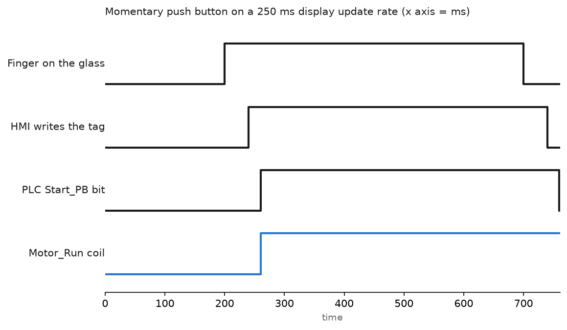
The chart shows why a momentary push button is not an instant thing. Press, poll, write, scan. Sixty milliseconds here, more on a busy network. It is fine for a start button and completely wrong for a two-hand safety control, which belongs in hardware.
Step 5: Protect against a stranded command bit
A Machine Edition momentary push button sets the bit while the finger is down and clears it on release. If the network drops while the button is held, nothing clears it. The controller sees a start command that never ends.
Put a heartbeat on the HMI and a watchdog in the controller:
(* MainTask, runs every scan. HMI increments HMI_Heartbeat every second *)
HMI_WD.TimerEnable := 1;
HMI_WD.PRE := 5000;
TONR(HMI_WD);

IF HMI_Heartbeat <> HMI_Heartbeat_Last THEN
    HMI_Heartbeat_Last := HMI_Heartbeat;
    HMI_WD.ACC := 0;
END_IF;

HMI_Comms_Lost := HMI_WD.DN;

IF HMI_Comms_Lost THEN
    Start_PB_HMI := 0;
    Jog_Fwd_HMI  := 0;
END_IF;
On the HMI side, one macro on a one second interval that adds 1 to HMI_Heartbeat is enough.
Step 6: Create the runtime and transfer it
- Application → Create Runtime Application. Pick the runtime version that matches the terminal firmware, not the newest one in the list.
- Save the
.MERsomewhere you will find it again. - Open ME Transfer Utility, browse to the file, select the terminal from the FactoryTalk Linx tree, tick Run application at startup and Replace communications, then Download.
- On the terminal, use the Configuration Mode menu to load the application if it does not start on its own.
Field notes
Slashes across every numeric display. A new PanelView showed //////// in place of numbers while the same application ran fine in Test Application. The Runtime (Target) tab of Communication Setup had no shortcut. One click of Copy from Design to Runtime and a re-download fixed it. If you only remember one thing from this article, make it that button.
The MER that would not load. A machine builder created the runtime in v13 and shipped it to a plant with terminals on firmware 11. The transfer utility refused the file with a compatibility message. Runtime applications are backwards compatible in one direction only. Create the MER for the oldest terminal firmware you have to support.
View Studio in demo mode on a Monday morning. After a server reboot, View Studio opened without activation and refused to create a runtime. The activation service had not restarted. The steps are in FactoryTalk Activation Manager Helper service is not running, and the manager itself is described in FactoryTalk Activation Manager.
A jog button that never let go. A palletiser operator held the jog button while an electrician unplugged the wrong Ethernet patch lead. The bit stayed set, the axis kept moving until the end of travel switch caught it. The heartbeat and watchdog in step 5 went into the plant standard the same week.
Renamed controller, dead screens. Someone renamed the controller from Line3 to Line_3 to match a new naming convention. Every direct reference on the HMI pointed at the shortcut, not the controller name, so the shortcut just had to be repointed. Tag-database style references would have needed rebuilding one by one.
Frequently asked questions
What is the difference between Machine Edition and Site Edition?
Machine Edition runs on a panel, one application, no client-server. Site Edition runs on PCs, supports multiple clients and a proper alarm and event system. The comparison is worked through in FactoryTalk View Site Edition and in FTView SE and FactoryTalk Site Client Edition.
Can one terminal talk to two controllers?
Yes. Add a second shortcut in Communication Setup and reference it by name, for example {::[PLC2]Tank_Level}. Remember to copy both to Runtime.
How do I trend a value on a PanelView?
Drop a Trend object and connect the pens to controller tags. The behaviour and the sample settings are the same idea as PLC trend page usage, tag history and monitoring.
Do I set up alarms in the PLC or the HMI?
Put the alarm condition in the controller so it is true regardless of who is watching, and let the HMI display it. Instruction level detail is in PLC alarm instructions.
What changes on a Siemens KTP700?
The HMI connection is created for you when you drag the CPU and the panel onto the same PROFINET subnet in the Devices and networks editor. Tags are created in the HMI tag table with an acquisition cycle, default one second. There is no separate runtime file, you download straight to the panel.
Next step
Get one screen working end to end before you build twenty. After that, the value the shift crew will ask for first is history, and the setup is in PLC trend chart settings and monitoring.