A CU240E-2 PN sits on the PROFINET IO system of a CPU 1516-3 PN/DP with G120 telegram 1 in its device view, the PLC is writing 16#047F to the control word and 8192 to the setpoint, and the motor does not move. Bit 6 of the status word is set. That bit is “switching on inhibited”, and the fieldbus function manual explains it in one sentence: it is only possible to switch on the motor after an OFF1 followed by ON.
The PLC powered up already sending ON. The drive never saw the OFF1.
Write 16#047E for one scan, then 16#047F again, and it turns. That is most of the article, and the rest is why: what telegram 1 actually carries, what each bit of the control word does, what the setpoint number means, and the one bit that produces a drive that reports ready and never moves. CU240E-2 PN control unit on a PM240-2 power module, STEP 7 Professional V17 with Startdrive, and every bit meaning below is from the SINAMICS G120 fieldbus function manual and the CU240E-2 operating instructions. The traces are worked from those definitions and the ramp parameters, not captured from a drive, and the figures say so.
Getting the drive into the project, and the three things that have to match
The drive appears in the hardware catalogue once Startdrive is installed, or, without Startdrive, once its GSDML is imported through Options, Manage general station description files. The manual lists a third route for a site with no internet: set p0804 = 12 with a memory card in the drive and it writes its own GSDML to the card. Drag the drive onto the PROFINET IO system, give it a device name and an IP address on the same subnet as the CPU, and add the telegram. For the CU240E-2 the factory setting of p0922 is 1, Standard telegram 1, PZD-2/2, and the factory macro on PROFINET units is default setting 7, “Fieldbus with data set switchover”, which wires the main setpoint p1070[0] to r2050[1], the second receive word. So a drive out of the box is already expecting exactly what the device view offers. The device overview then shows the telegram with its I address and Q address ranges, four bytes each way. The fieldbus manual’s own commissioning checklist is four questions, and every stuck drive I have been called to fails one of them. Is the converter connected to the bus? Do the IP address and device name in the converter and in the control match? Is the same telegram set in the converter as in the controller? Are the signals interconnected in the drive the way PROFIdrive expects? On a replacement drive the second question has a twist the manual states plainly: the replacement converter is assigned the device name from the IO controller, not from its memory card and not from the programming device, so a spare that came with somebody else’s name on it is not a problem, and a spare that you carefully named by hand before fitting was wasted effort.
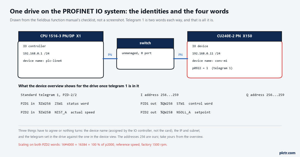
Our drawing from the manual’s checklist, not a screenshot. The addresses are the ones this project used; yours come from the device overview.
Name and IP match, telegram matches, and four words appear in the overview.
Two go out: STW1 the control word in the first output word, NSOLL_A the speed setpoint in the second. Two come back: ZSW1 the status word, NIST_A the actual speed. In this project that is %QW256, %QW258, %IW256 and %IW258, and the drive interconnects them itself, the operating instructions say, the moment a telegram is selected: r2050 for received words, p2051 for sent ones, locked until you set p0922 to 999 and p2079 to the telegram number to extend it. Leave that alone on a first commissioning.
G120 telegram 1: the control word, bit by bit
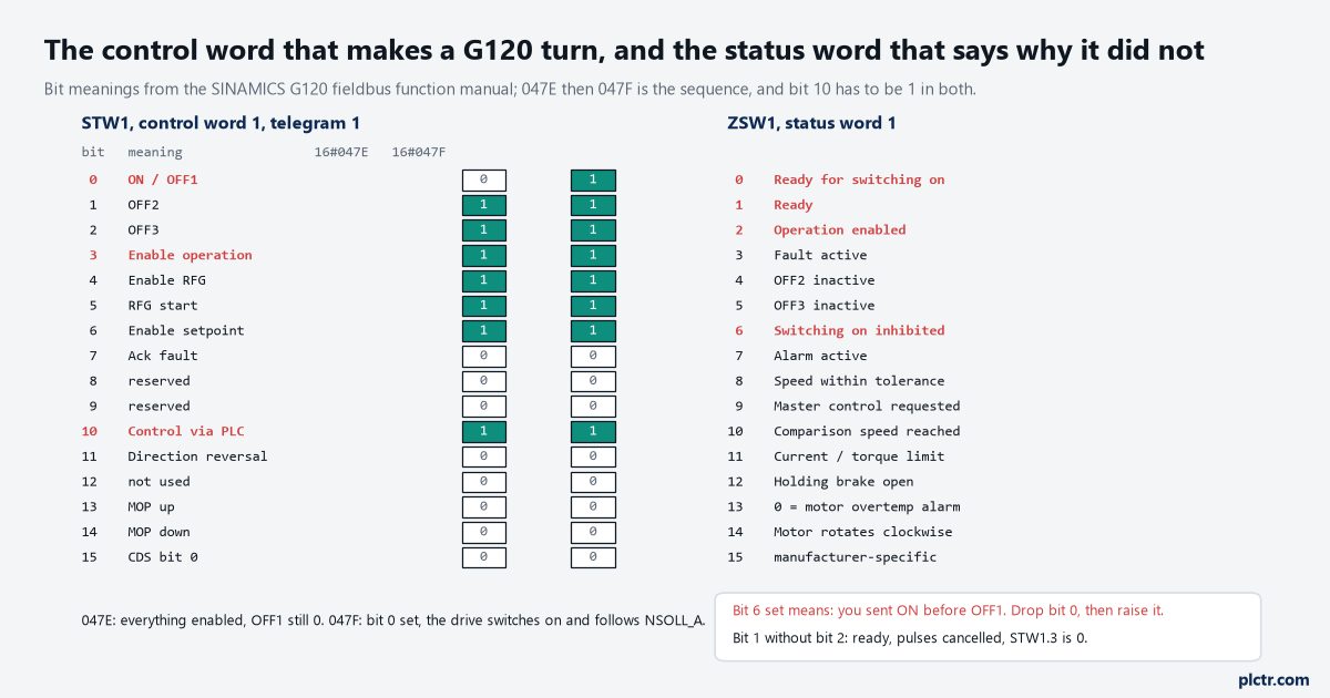
Bit meanings from the fieldbus function manual. Bits 0, 3 and 10 are the three that stop a first start; bits 0, 1, 2 and 6 of the status word are the ones that explain it.
Bit 0 is ON/OFF1. At 0 the motor brakes on the ramp-down time p1121 and switches off at standstill; at 1 the converter goes to ready, and, the manual adds, if bit 3 is also 1 it switches the motor on. Bit 1 at 0 is OFF2: switch off immediately and let the motor coast. Bit 2 at 0 is OFF3, the quick stop on its own ramp p1135. Bit 3 is enable operation, and at 0 the pulses are cancelled. Bits 4, 5 and 6 enable the ramp-function generator, let it run and enable the setpoint; leave any of them at 0 and the ramp output is forced to zero, frozen, or ramped down. Bit 7 acknowledges a fault on a 0 to 1 edge, with a detail worth knowing: if the ON command is still active when you acknowledge, the converter goes to switching on inhibited, which is bit 6 again. Bit 10 is control via PLC, and the list manual is emphatic about it under p0854: if a controller is present, STW1.10 must be set to 1 so that the received data is updated at all, regardless of anything else. Bit 11 inverts the setpoint. Bits 13 and 14 are the motorised potentiometer and do nothing in telegram 1.
Put those bit meanings together and the two values fall out.
16#047E is bits 1, 2, 3, 4, 5, 6 and 10 set and bit 0 clear: every enable present, OFF1 still applied, drive ready for switching on. 16#047F is the same word with bit 0 set. The sequence is 047E, then 047F, and the drive answers 047E with ZSW1.0, ready for switching on, and 047F with ZSW1.1 ready and ZSW1.2 operation enabled, at which point NIST_A starts climbing. Which is why the opening fails: a PLC whose logic sets the run bit from a maintained selector switch sends 047F from its first scan. The drive powers up, sees ON with no preceding OFF1, and raises bit 6. The fix in logic is a start edge, not a start level: the one push button start and stop shape, or simply forcing bit 0 low for a scan on first cycle. And when a fault has been acknowledged with the run command still present, the same bit comes up for the same reason, and the same 047E clears it.
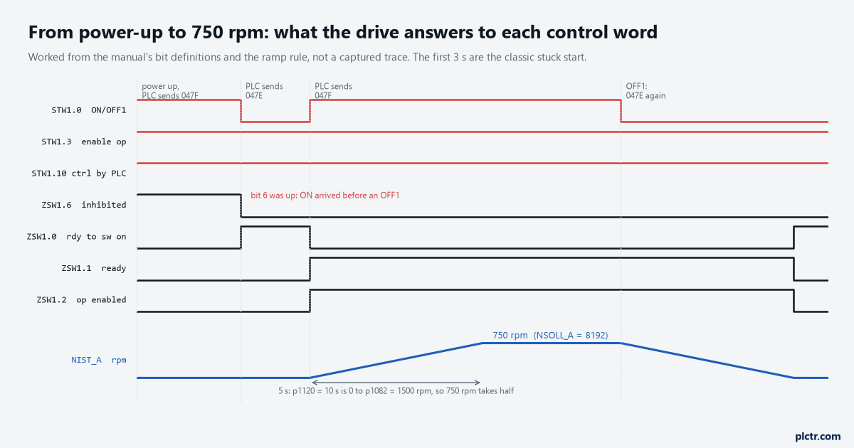
Worked from the bit definitions and the ramp rule, not a captured trace. The first three seconds are the stuck start from the opening.
The drive also watches the other direction. F07220 is the fault the list manual files under master control by PLC missing, and its remedy is to take bit 0 to 0, which is the drive telling you that control went away while ON was still applied.
The setpoint is a percentage of p2000, not a speed
8192 in the setpoint word is not 8192 rpm, and it never was.
NSOLL_A and NIST_A are scaled the same way, and the list manual states it under p2000: the reference quantity corresponds to 100 percent, or 4000 hex as a word, 4000 0000 hex as a double word. p2000 is the reference speed, factory setting 1500 rpm, so 16#4000 = 16384 is 1500 rpm, 8192 is 750 rpm, and 4096 is 375. A negative value is the other direction, or leave the number positive and set bit 11. The PLC side is one line of arithmetic, rpm times 16384 divided by p2000, and then a conversion to Int that has to be explicit: the IEC check refuses a Real into an Int implicitly, so it is REAL_TO_INT or ROUND, on purpose. How fast it gets there is p1120 and p1121, ramp-up and ramp-down, factory 10 s each, and the operating instructions define them from zero to the maximum speed p1082, which is also 1500 rpm from the factory. So a setpoint of 750 rpm reaches speed in 5 s, not 10, and if the extended ramp-function generator is selected, p1130 and p1131 add rounding at each end and the effective time is p1120 plus half their sum. OFF3 has its own ramp, p1135, and bit 2 uses it. None of this is in the telegram. It is in the drive, and it is the reason two identical machines with identical PLC programs accelerate differently after somebody has been through the parameters on one of them.
The actual value comes back on the same scale: Int times p2000, divided by 16384.
Bit 3, the one that gives you a ready drive and a free shaft
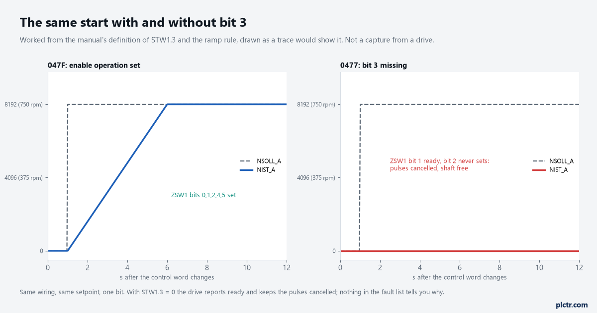
Worked from the manual’s definition of STW1.3 and the ramp rule, drawn as a trace would show it. Not a capture.
Clear bit 3 and send 0477 instead of 047F. The manual’s table for bit 0 says the converter goes to ready, and switches the motor on only if, in addition, bit 3 = 1. So the drive answers with ZSW1.1 ready, and bit 2, operation enabled, never comes. No fault, no alarm, ZSW1.3 stays clear, the diagnostics buffer on the CPU is empty and the fault list on the operator panel is empty, because from the drive’s side nothing has gone wrong: it has been told to be ready and not to run, and it is doing precisely that. The shaft turns by hand. The word looks right at a glance because 0477 and 047F differ in one nibble and most people read the leading 047.
Read the status word in binary before reading anything else.
Bits 0, 1 and 2 climbing one after the other is a healthy start. Bit 1 set with bit 2 missing is bit 3 of the control word. Bit 6 set is a missing OFF1. Bit 3 set is a real fault, and only then is the fault list worth opening.
What everybody checks first
The ramp. When the motor does not move, the first parameters people open are p1120 and p1082, on the theory that the drive is ramping so slowly or to such a low limit that nothing is visible. It is almost never that on a fresh drive, because the factory values are 10 s and 1500 rpm, and a motor at 375 rpm after 2.5 s is not subtle. Then the wiring gets checked, then the power module gets checked, and on one job the drive got swapped before anybody looked at the status word, which had been saying switching on inhibited the whole time.
Look at ZSW1 first: it is the drive’s own account of what it was told.
Before you leave it running
Two behaviours follow from the bit table and are worth reasoning through before the machine is handed over, because neither is written in the PLC program. When the CPU goes to STOP, its outputs stop being written and the drive’s receive words go to 0, and a control word of 0 has bit 1 at 0, which the manual defines as OFF2: switch off immediately, motor coasts. A CPU STOP therefore coasts every motor on the bus rather than ramping it, and a load that must never coast, a hoist or a long conveyor with product on it, needs that thought about at the drive end, not the PLC end. That is my reading of the bit table, not a sentence from the manual, and it is worth confirming on the bench with nothing on the shaft. The second is the acknowledge: bit 7 with ON still present leaves the drive inhibited, so a reset button that shares a rung with the run command produces a drive that is reset and will not start until somebody cycles the start.
Neither behaviour is in the PLC program, and both will be blamed on it.
Then measure it. Put ZSW1, NIST_A and the control word into a watch table on the CPU and press the button while you watch the three of them, in that order. When one drive has to carry more than one motor, two motors on one VFD is where that decision lives, and the motor control overview with the G120 wired for terminal control is the other way of commanding the same drive when there is no PROFINET at all.