The station is an IM 155-6 PN with an ET 200SP F-DI 8x24VDC HF in slot 3, the CPU is a 1515F-2 PN on TIA Portal V17, and the hardware compiles clean with a warning that says the F-module has no valid PROFIsafe address yet. The guard door on channel 2 is wired as two NC contacts, the F-DI DB has appeared in the project tree with a name like F00010_F_DI_8x24VDC_1, and the properties tab has thirty fields on it of which three decide whether this door works: the F-destination address, the sensor evaluation, and the discrepancy time. Everything below is that station. The parameter names are the ones the SIMATIC Safety manual uses; the module’s own equipment manual, which I could not open for this article, is the place for the terminal assignment and the sensor-supply and short-circuit-test settings, and I say so where it matters.
Three fields. The rest have defaults you can leave.
The address: what it is, where it lives, and why the spare does not care
An ET 200SP F-module has no DIP switch. That one fact rearranges everything you know from ET 200S.
On the older modules the F-destination address was set on a switch before the module went in, and the manual still describes that for ET 200S, ET 200pro and the S7-300 F-SMs: up to 1022 addresses, set on the hardware, unique network-wide. ET 200SP, ET 200MP and the S7-1500 F-modules are PROFIsafe address type 2 instead, which the manual defines as unique by the combination of F-source address and F-destination address; the F-source address is the F-CPU’s Central F-source address parameter, one per CPU, and the F-destination address is assigned per module in the hardware configuration and must not collide with any type 1 module on the same network. TIA picks the F-destination address for you when you drop the module in, starting at the low limit in the F-CPU properties – the manual’s example uses 100 to 199 – and warns at compile if it has to go outside the range. Then comes the step people miss. The address in the project is not yet in the module; you assign it online, from the device view, by identifying the module – the manual’s procedure has you confirm the right one by its LED before you assign – and the address is written into the F-coding element, which sits in the BaseUnit, not in the module. The manual’s list of when the address does not need assigning again is the useful half: power off and on, replacing the F-module itself without a PG, replacing the BaseUnit, a new BaseUnit inserted in front of the module, repair of the interface module. The list of when it does: a module placed later during first commissioning, a deliberate change of the address, a change of the CPU’s central F-source address, replacement of the coding element, and commissioning the next machine of a series. So a spare F-DI from stores, pushed onto the same BaseUnit, comes up with the right address and nobody opens a laptop. A spare BaseUnit with its own coding element does not.
The address is in the BaseUnit. Write that on the inside of the panel door.
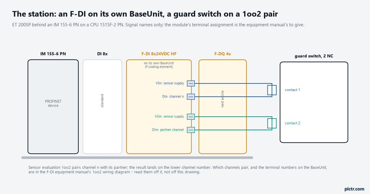
Signal names only. Which channel pairs with which, and which terminal is which on the BaseUnit, is the equipment manual’s wiring diagram to give; the station layout and the address rules above are the SIMATIC Safety manual’s.
1oo2 in the ET 200SP F-DI or 1oo2 in the program
Two ways to evaluate the pair, and they put the discrepancy fault in different places.
With sensor evaluation set to 1oo2 on the module, the manual says two channels are grouped into one channel pair and the result of the evaluation is usually provided under the address of the channel with the lower channel number – so you read channel 2, its value status is the pair’s value status, and the partner channel’s address is not to be used in the program at all; the compiler warns if you do. A discrepancy between the two contacts that lasts longer than the discrepancy time is then a channel fault, the same class as a wire break or a short-circuit: the pair passivates, its value goes to the fail-safe 0, its value status drops, and how it comes back depends on the channel-fault acknowledge setting. That is the compact version, and on an S7-1500F it is the one I would build first, because the door is one bit in the program and one line in the safety summary. The other way is to leave both channels single and call EV1oo2DI in the safety program with the two channel values on IN1 and IN2, and the manual describes what you get for the extra block: DISCTIME up to 60 s, DISC_FLT as a stored discrepancy error with a restart inhibit, ACK_REQ when the discrepancy has cleared and an acknowledgement is needed, and an ACK input that takes a rising edge when ACK_NEC is 1. The block’s warning S033 is the same one every Siemens safety block carries – ACK_NEC may only be 0 where an automatic restart is otherwise excluded – and there is a second one worth reading twice: Q can never go to 1 if DISCTIME is set below 0 or above 60 s, and the call interval of the safety program must be shorter than DISCTIME. When the pair is evaluated in the program, the door being open and the door being faulted are two different outputs you can put on the HMI. When it is evaluated in the module, they are one passivated channel and a diagnostic buffer entry.
Both are legitimate. Pick by who has to understand the fault at 3am: the program version tells them, the module version makes them read the buffer.
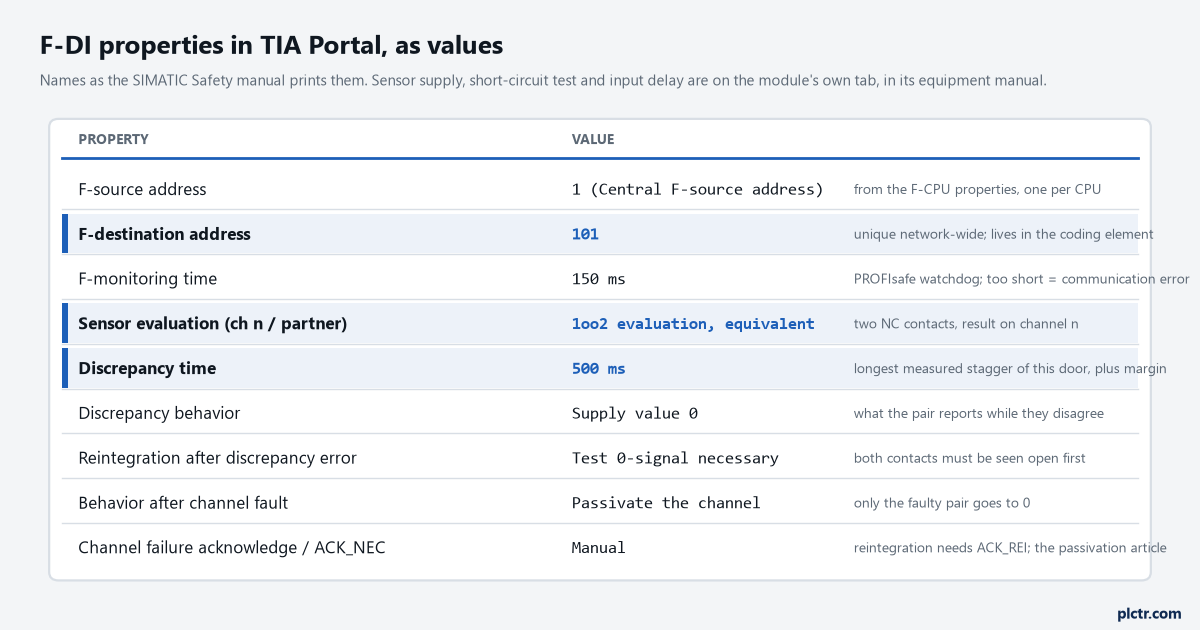
The three highlighted rows are the article. F-monitoring time and the acknowledge setting have consequences of their own; the passivation article covers the second.
The discrepancy time is a measurement, not a preference
Five hundred milliseconds is on this door because the door was measured, and the number is not transferable.
The manual’s glossary says what the timer is for: the discrepancy analysis starts when the two associated signals differ, and if the difference has not gone away when the discrepancy time expires there is a discrepancy error. The right value is therefore the longest stagger between the two contacts that a person can produce by operating the door normally, plus a margin, and nothing longer. The Rockwell Guard I/O manual says the same thing from the other side of the fence – do not set the discrepancy time longer than necessary, because a second demand inside the window faults both channels – and the discrepancy time article works through measuring it on a 1791ES; the method is identical here. Trend both channels with a 10 ms or faster sample, open and close the door thirty times at every speed a person uses including the slow push with a trolley, and read the longest gap. On this door the gap was 40 to 180 ms with one outlier at 310 ms when the door was bounced against its stop, so 500 ms covers it with room. What people set instead is 3000 ms because a training course used it, and then a door that is slammed and caught produces two demands inside one window and a fault nobody can reproduce on Monday. Two parameters sit next to it in the manual’s vocabulary and want a decision each: discrepancy behaviour, which is what the pair reports while the two disagree – supply value 0 or the last valid value – and reintegration after a discrepancy error, where “test 0-signal necessary” means both contacts have to be seen open before the pair is trusted again. Leave the first at 0 unless you can argue why the door should read closed while its contacts disagree. Leave the second at “necessary”.
Measure, add a margin, write the measurement next to the value in the safety summary.
What a discrepancy trip looks like from the CPU
Nothing in the buffer says “discrepancy” in large letters, so know what to look for.
The pair’s channel value goes to 0, and if channel-granular passivation is configured only that pair goes, the other six channels keep working. The value status bit for the channel drops to 0, and the Siemens programming guideline lists the four ways to see a passivated channel: value status false, QBAD in the F-I/O DB true, the channel and module LEDs red, and an entry in the diagnostics buffer. In the F-I/O DB, QBAD goes to 1 and when the contacts agree again ACK_REQ goes to 1, which is the module saying the fault has cleared and it is waiting to be told. What happens next is the acknowledgement setting: with channel failure acknowledge on manual, or ACK_NEC at 1 in the F-I/O DB, the channel stays at 0 until a rising edge on ACK_REI; with automatic, it comes back by itself, and the manual’s warning S045 says that is only allowed where automatic reintegration is permitted for the process. The door channel staying at zero after the door is closed and the contacts agree is the single most common Siemens safety question there is, and it has its own article, because the answer is not on this properties tab.
Set the acknowledge to manual, and wire the acknowledgement before you test the door, not after.
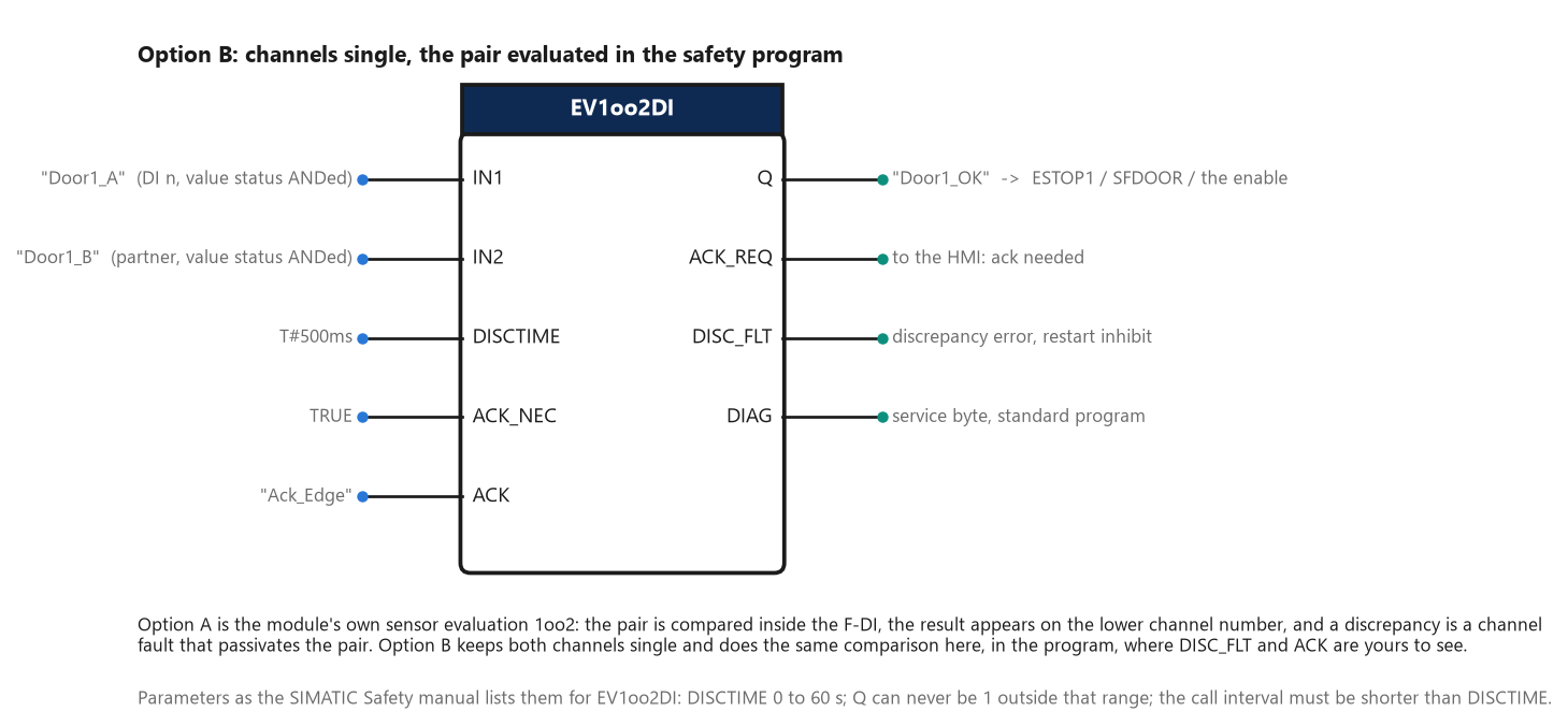
Option B. The same door with the discrepancy evaluated in the safety program, so the fault and the acknowledgement are visible as block outputs instead of as a passivated channel.
The order that avoids a second download
The sequence the manual’s own procedure implies, written out as the day goes.
Set the F-CPU’s central F-source address and its F-destination address range first, before any F-module is placed, so the addresses TIA assigns do not have to change later. Place the F-DI, set the sensor evaluation on the pairs you use and disable the channels you do not – the manual says to address only channels enabled in the hardware configuration, and the compiler warns otherwise. Set the discrepancy time from the measurement, the discrepancy behaviour, the reintegration condition, and channel failure acknowledge to manual. Compile the hardware, download it, and only then go online to identify and assign the PROFIsafe address, because the assignment is against the downloaded configuration. Then compile the safety program, and read the safety summary: the manual says the F-source and F-destination address columns in the device view are for information only and it is the safety summary that has to be checked at acceptance. Then wire the acknowledgement. Then open the door.
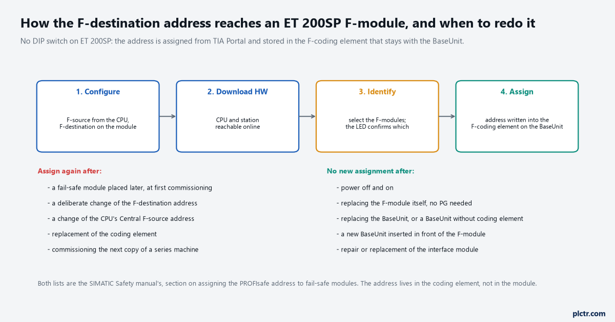
The address lives in the coding element on the BaseUnit. That is why a spare module needs no PG and a spare BaseUnit does.
Next step
Open the F-CPU properties and read the central F-source address and the F-destination range before you place the module, then place it, and then measure the door before you type a discrepancy time. The acknowledgement that brings a passivated channel back is the passivation and reintegration article, which follows this one; the wiring that lets the module see a short between the two contact wires is in the cross-fault detection article; and whether this machine wanted an F-CPU at all rather than a 3SK1 relay is the relay-or-controller question. If you are coming from GuardLogix, the same door on a 1791ES is wired end to end in the dual-channel interlock walkthrough, and the vocabulary maps one to one: sensor evaluation is Point Operation Type, the F-destination address is the SNN plus node, and value status is the individual input status bit.
Three fields, one measurement, and the address in the BaseUnit. The other twenty-seven can wait.