A one button start and a one button stop written as separate rungs both end in OTE Motor, and the second one wins every scan, which is why the panel lamp flickers at scan rate and the contactor never pulls in. Two things fix it: an ONS or OSR so the press lasts one scan, and one rung that computes the new state and writes Motor exactly once.
That is the whole answer, and it fits in two rungs.
The reasons it goes wrong are worth twenty minutes, because the same mistake hides in Structured Text, on HMI buttons and inside a press that bounces.
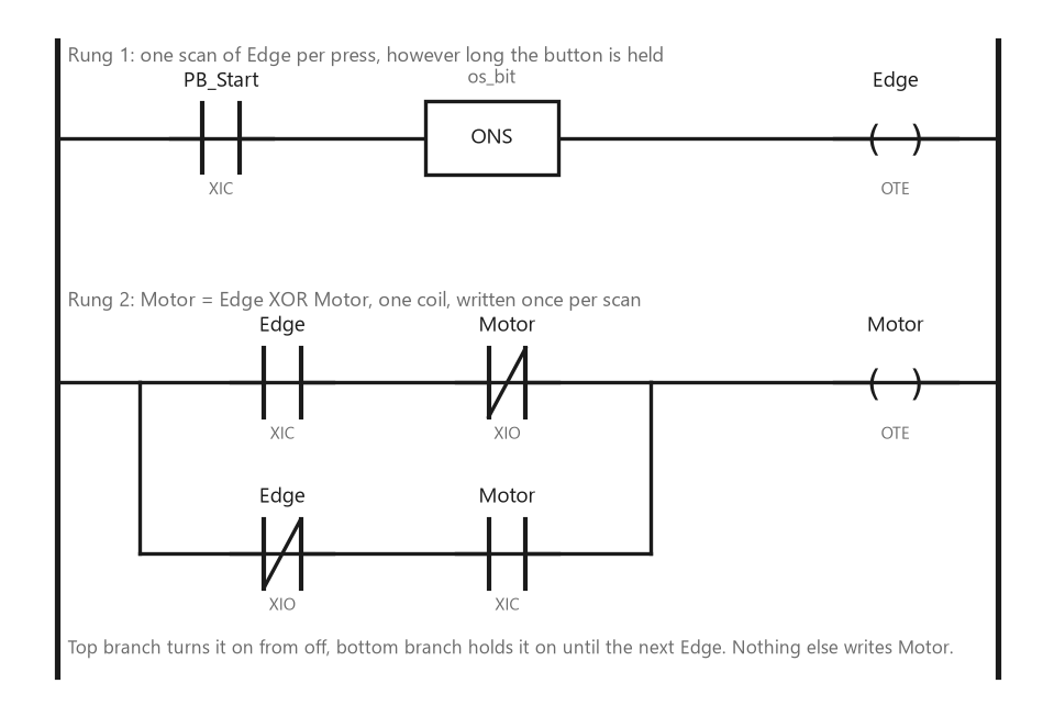
Two rungs, one coil. The top branch turns Motor on from off, the bottom branch holds it on until the next Edge, and nothing else in the program writes Motor.
Why a one button start and stop written twice cancels out
Ladder is evaluated top to bottom and the last coil written is the one that reaches the output image. Put the start rung above the stop rung with the same OTE Motor on both:
XIC PB_Start  XIO Motor  OTE Motor     // start
XIC PB_Start  XIC Motor  OTE Motor     // stop
Trace one scan with the button pressed and the motor off. Rung one sees Motor false, its condition is true, and it writes Motor true. Rung two, later in the same scan, sees Motor true, its condition is also true, and it writes Motor true again. Next scan, button still pressed: rung one sees Motor true, XIO Motor opens, the rung is false and the OTE writes Motor false; rung two then sees Motor false and writes false as well.
The second rung never decides anything; it re-writes whatever the first one just wrote, and the first one flips the motor on every scan the button is held.
A finger on a button is 100 to 300 ms and a typical scan is 5 to 20 ms, so one press is seen by ten or more scans. What comes out of the output image is Motor flipping at scan rate for as long as the button is down, and the state it ends in depends on whether the press covered an odd or an even number of scans. At a 10 ms scan the contactor coil is being driven with a 50 Hz square wave, the auxiliary contact chatters, and the fault gets reported as “sometimes it starts and sometimes it does not”. Double coil is the name people give this, and it is really two faults stacked. The scan-rate flip is the level-versus-edge fault. Writing one output from two places is the double coil, and it is the reason nobody can read the program a year later. Fix both.
The one-shot is the whole trick
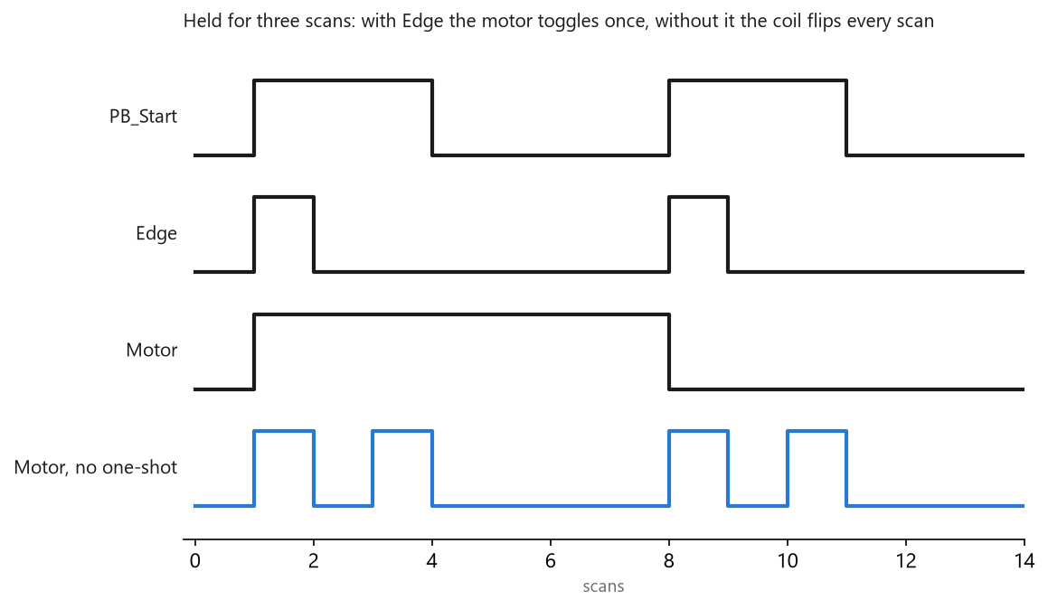
The same press, with and without the one-shot. Edge is true for exactly one scan per press, so Motor changes exactly once. Without it the coil flips on every scan the button is held.
On a Logix controller the instruction is ONS, and the reference manual defines it in one line: it makes the remainder of the rung true each time rung-condition-in transitions from false to true. It needs a storage bit, a BOOL tag of your own that holds the rung-condition-in from the last execution, and that bit must not be used anywhere else. OSR does the same job and writes a named output bit for one scan, which reads better when the edge is consumed in another rung; OSF fires on the release instead of the press, which is the right choice for a button that is meant to act when let go. On an S7-1200 or S7-1500 the equivalents are the P_TRIG box and the P contact, both of which take an M_BIT operand, and R_TRIG, which carries its own instance. The S7-1200 manual is strict about the memory bit: because it must be maintained from one execution to the next, use a unique bit for each edge instruction and do not use it anywhere else. Inside a function block that is called more than once, that unique bit has to be a Static, or you have the second instance following the first.
Then the state, which is the part that gets written from two places.
The rung in the figure is an exclusive OR written in contacts: Motor comes on when Edge is true and Motor was off, and stays on when Edge is false and Motor is on. One coil, evaluated once per scan, and the result is Motor flipped on every Edge and held otherwise. In Structured Text on either platform it is a single line:
Motor := Motor XOR Edge;
with Edge coming from OSR on Logix or the Q of an R_TRIG multi-instance on S7. If the XOR reads as a trick, write the long form, which is what the ladder does:
IF Edge THEN
    Motor := NOT Motor;
END_IF;
Both are one assignment to Motor, and that is the property to protect.
Every other way of doing this that works — an OTL/OTU pair driven from two edge rungs, a CTU counting presses and testing bit 0 of the accumulator, a two-state case statement — also writes the state from exactly one place, and every way that does not work writes it from two.
The press that arrives three times
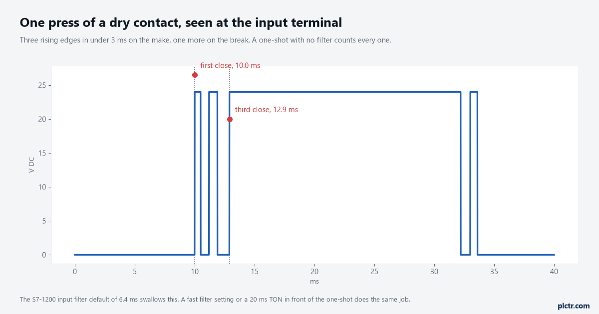
A dry contact does not close once. Three rising edges inside 3 ms is ordinary for a panel push button, and a one-shot with nothing in front of it will count every one of them.
A one-shot fixes the scan-rate problem and introduces the next one: it is now faithful to every edge, including the ones the contact makes on its own. Mechanical contacts bounce for a few milliseconds on closure. Three closes means three edges means three toggles, which lands the motor in the opposite state from the one you wanted, and only on some presses, which makes it look like a wiring fault. Two places to kill it. The input card’s filter is the first. The S7-1200 manual states the default digital input filter time as 6.4 ms and says in as many words that it blocks unwanted transitions from typical mechanical contacts: a change has to persist for about 6.4 ms to be seen at all, and a pulse shorter than that is not seen. Leave that default alone on a push button input. Somebody who dropped it to 0.2 ms for an encoder on the same card has just un-debounced every button on it. Logix input modules have their own filter settings per point group, and the same reasoning applies: fast filters belong on the channels that need them. The second place is a TON between the input and the one-shot, 20 ms preset, and the one-shot on the timer’s DN. That costs 20 ms of response nobody will feel and it works on a card whose filter you cannot touch. A TOF on the release side does the same for the break bounce, if OSF is what you are triggering on.
The first scan, and why the two platforms differ

Prescan on Logix pre-arms the storage bit, so a button held through power-up produces no edge. On S7 the edge instruction evaluates from the first execution, so a held button at start-up is an edge unless the block handles it.
Power up with a thumb on the button and the two families do different things, and both are documented.
On Logix, the ONS execution table reads: on prescan, the storage bit is set to true to prevent an invalid trigger during the first scan. OSR does the same and clears its output bit. So a button that is already pressed when the controller goes to RUN does not toggle the motor; the storage bit is already true, and the first real edge is the next press. You get that for free. On S7 you do not. The S7-1200 manual’s note under the edge instructions is the part to read twice: edge instructions evaluate the input and memory-bit values each time they are executed, including the first execution, and you must account for the initial states of the input and memory bit in your program design either to allow or to avoid edge detection on the first scan. An M_BIT that starts at 0 after a start-up, against an input that is already 1, is an edge, and a motor that starts because someone was leaning on the panel during a power cycle is not a story anyone wants to tell. Set the edge memory to the input’s state in the startup OB, or gate the toggle behind a “first scan done” Static that the block sets at the end of its first pass.
Where a toggle button does not belong
A single button that both starts and stops is fine for a work light, a conveyor in a cell with no one near it, a fan. It is the wrong device for anything where a stop has to be a stop. The stop function on a machine goes through a normally closed contact into a dedicated input, or through the safety circuit, and the toggle button only ever sets the running state that the stop can override. That means the toggle rung gets one more contact, XIC Stop_OK in series with the top branch and the bottom branch both, so a stop drops Motor regardless of what the toggle thinks. The one-button pattern is about convenience, not about removing the stop button, and a proper start/stop circuit still has one. The HMI version of this question has one extra wrinkle. A momentary button on a panel writes the tag true on press and false on release, over a connection with its own update rate, so the “press” the PLC sees can be one scan or fifty. The one-shot handles that. What it does not handle is the release being lost when the panel drops off the network with the tag still true, which is why a momentary HMI button feeding a toggle should be timed out in the PLC — a TON on the tag, and if it stays true for more than a couple of seconds, treat it as stuck and ignore it until it clears.
What to check on the machine
Put the button, the Edge bit and Motor on one trend at the scan rate, or on a watch table if that is what you have, and press once. Edge should show one scan of true per press, no matter how long you hold. If you see two or three, the bounce section applies and the filter time on that input is the first number to read. Then power-cycle with the button held and watch whether Motor comes up true; on S7 it will unless you handled it, and now you know where.