The guard on the case packer came off its 440R-S12R2 on a Saturday and went onto a 1791ES-IB8XOBV4 under a GuardLogix 5580, same tongue switch, same two 100S-C09 contactors, and the first time the door was closed the DCS instruction reported Fault Code 16#4000 and would not take a reset. Channel A active, channel B still safe when the Discrepancy Time ran out. The switch had not changed. The two contacts in a tongue switch have always closed a few tens of milliseconds apart as the actuator slides home, and the relay’s spec for input simultaneity is the word infinite, so in three years nobody had known. The DCS had 50 ms in it, copied from an E-stop elsewhere in the project, and the contacts on this switch arrive 90 ms apart when the door is closed slowly. That is the first thing to understand about moving a 440R relay to GuardLogix: the rung replaces the relay’s decision, and it makes decisions the relay never made. What follows maps each terminal of the relay onto the operand or the module parameter that took its job, and then lists what stayed exactly where it was – which is most of the panel.
The switch, the contactors and the mirror contacts do not move. The decision does, and it gets stricter.
440R relay to GuardLogix: where each terminal went
Start with the two things the relay did that people assume the controller does, and which the module does instead.
The pulse-test sources S11 and S21 became test outputs T0 and T1 on the module, each one configured as Pulse Test Output and each one carrying 24 V with a 500 µs dip every 150 ms, per 1791ES-UM001H, against the relay’s 1.5 and 3 ms dips every 13.6 ms. The inputs S12 and S22 became I0 and I1, configured with Point Mode Safety Pulse Test and the Test Source set to T0 for I0 and T1 for I1, and the manual’s footnote is the one to remember: pick the wrong test source and the result is pulse-test failures on that input, which is the four-flash cross fault of the relay wearing a different badge. The relay’s cross-fault detection lives in the module now, and the DCS only sees its result as the Input Status operand going false, Fault Code 16#20. The safety outputs 13/14 and 23/24, two positive-guided relays in series behind each pair of terminals, became the bipolar output pairs O0 and O1, sourcing and sinking transistors on each coil, Point Mode Safety Pulse Test, 700 µs off every 600 ms while on. The contactor coils sit where they sat; what changed is that they are now 24 V DC loads on a solid-state pair rather than a 250 V AC 1.5 A dry contact, and a coil that is not 24 V DC needs a safety-rated interposing relay in between, with everything the test pulse article says about what sits between a pulsed output and a coil. The monitored reset loop into S34 – button, K1 mirror contact, K2 mirror contact in series – was one wire and became three inputs: the button on I2 from T2, K1’s mirror contact on I3 from T3, K2’s on I4 from T4, because the controller wants to know which of the three opened. Y32, the auxiliary that was on when the outputs were off, is simply the DCS’s O1 tag read by a standard routine; safety tags are readable from standard logic, and there is nothing to wire.
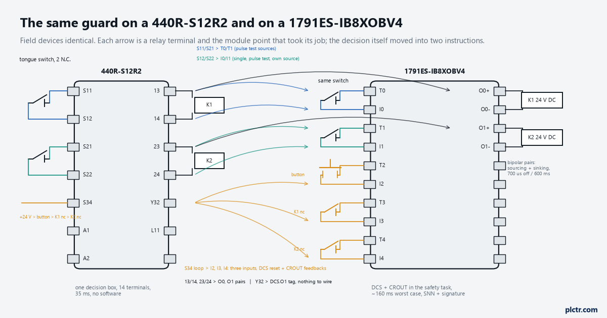
One wire into S34 became three inputs. Two dry contacts became two pulsed 24 V DC pairs. The field devices did not move.
The one item with no arrow is the relay’s internal redundancy. Its two relays in series were the Category 3 structure’s second channel on the output side, and on the module that is the bipolar pair plus the second contactor, which is the structure the Safebook draws for a single tongue switch with two monitored contactors. Same structure, different box, and the PL claim has to be re-evaluated for the new box rather than carried across.
What the DCS does that the relay did not
Three operands, and each one is a decision the relay never made.
Input Type Equivalent with a Discrepancy Time, 5 to 3000 ms, is the first. The relay would accept the two channels arriving any distance apart in time, and 1756-RM095 says the instruction faults with 16#4000 or 16#4001 when the two are inconsistent for longer than the setting, and with 16#4002 or 16#4003 when one channel goes to the safe state and back while the other stays active – the door pushed shut twice, or a contact that bounced, both of which the relay simply followed. The number wants measuring on this switch, not copying, and the discrepancy time article is the method; on this door 250 ms covered the slow close with room, and 50 ms did not. And the module has a discrepancy time of its own, on the Input Configuration tab, which the Guard I/O manual warns masks the instruction’s fault from the controller if you set it there: leave the module points Single and let the DCS do the pair, which is what RM095 asks for in as many words. Restart Type is the second. The relay’s MM position wanted a press of 250 to 3000 ms and acted on the release; the DCS’s Manual restart wants an OFF-to-ON transition of its Reset operand while the enabling conditions are met, and the footnote under that operand says some standards require the transition to be monitored and additional logic may be needed. So the rung does not replace the relay’s press-length check. You write it, as the one-shot in the rising-edge reset article, and the same Reset_OS bit feeds the DCS and the CROUT. A plain XIC of the button on the Reset operand gets you Diagnostic Code 16#05, Reset held ON, from the first taped-down button. Cold Start Type is the third, and the relay had no equivalent: Manual means the inputs have to go through the safe state after power-up or after an Input Status fault before O1 can energise – the door has to be opened and closed once after every download and every module fault – and Automatic does not ask. Manual is the right default for a guard; write on the drawing that a download means a door cycle, or the first call after a firmware upgrade is “the guard will not reset”.
Discrepancy time, restart type, cold start. None of them exist on the relay, and all three produce a call in the first week.
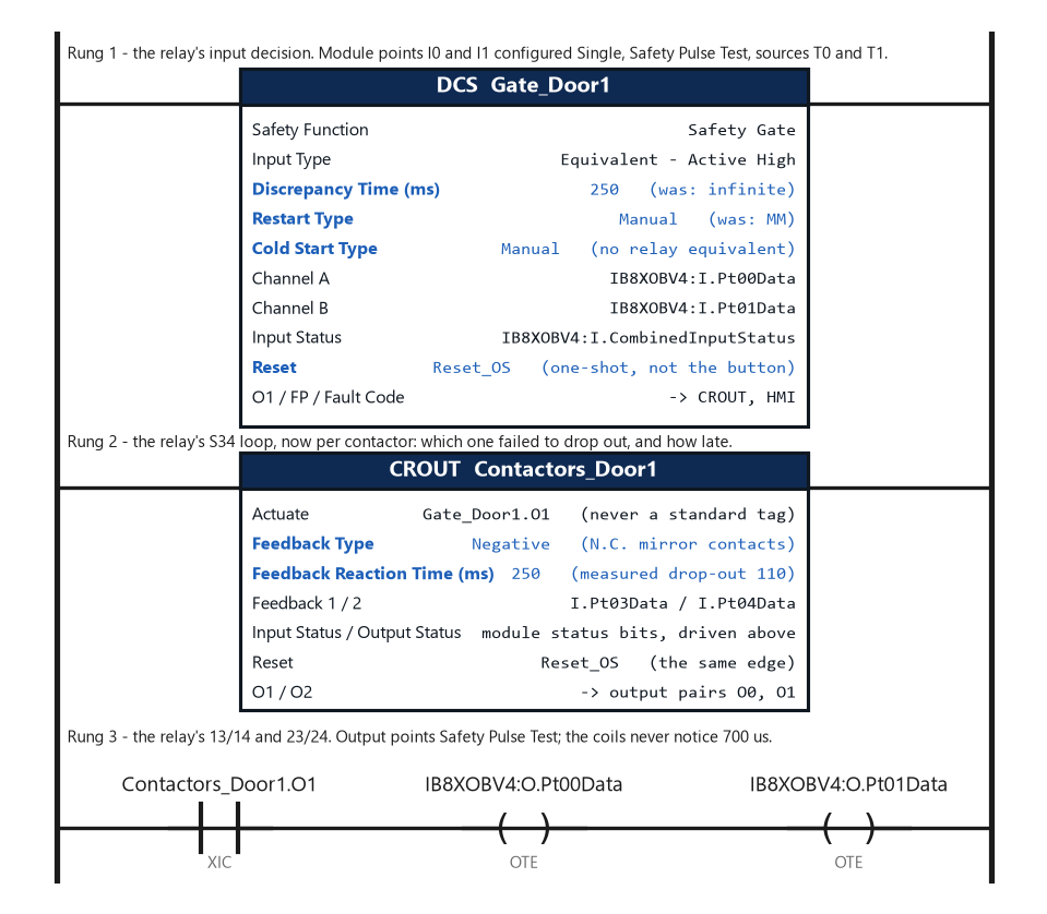
The relay’s whole decision is these two instructions. The one-shot that makes Reset_OS is the third rung the relay never needed, because it did the press check itself.
The contactor feedback became the CROUT. The relay’s S34 loop only knew that both mirror contacts and the button were closed; the CROUT reads each feedback against its own output within a Feedback Reaction Time, reports which contactor failed to drop out, and needs Feedback Type Negative for N.C. mirror contacts – the operand that produces most “faults on reset” calls, worked through in the mirror contact article. Actuate comes from the DCS’s O1, never from a standard tag, and Input Status and Output Status take the module’s status bits above the instruction.
What the move costs in time
The relay’s response time is 35 ms, from an input opening to the safety contacts open. The controller’s is a chain, and 1756-RM012J lists its links: the input device, the input connection reaction time limit, the safety task period plus its watchdog, the output connection reaction time limit, and the output device. Put the manual’s defaults in. The Guard I/O input reacts in 16.2 ms plus whatever input delay you set. The input CRTL is the RPI times the sum of the timeout multiplier and the network delay multiplier, and at the defaults of 10 ms, 2 and 200% that is 40 ms, which the manual flags with an IMPORTANT to say that if you leave the defaults alone, 40 ms is the number that goes into the calculation. A 20 ms safety task with a 20 ms watchdog is 40 more. The output CRTL is the safety task period times the same sum less one: 20 × 3, 60 ms. The output module reacts in 6.2 ms. That is 162 ms worst case against 35, and the contactor’s own drop-out is on top of both, unchanged. None of those are typical figures; they are the limits the design has to use, and the manual’s second IMPORTANT says the defaults sometimes have to go up to stop connection loss to the I/O, at which point the new figure goes into the same sum. A guard whose distance from the hazard was set against 35 ms is now four and a half times slower on paper.
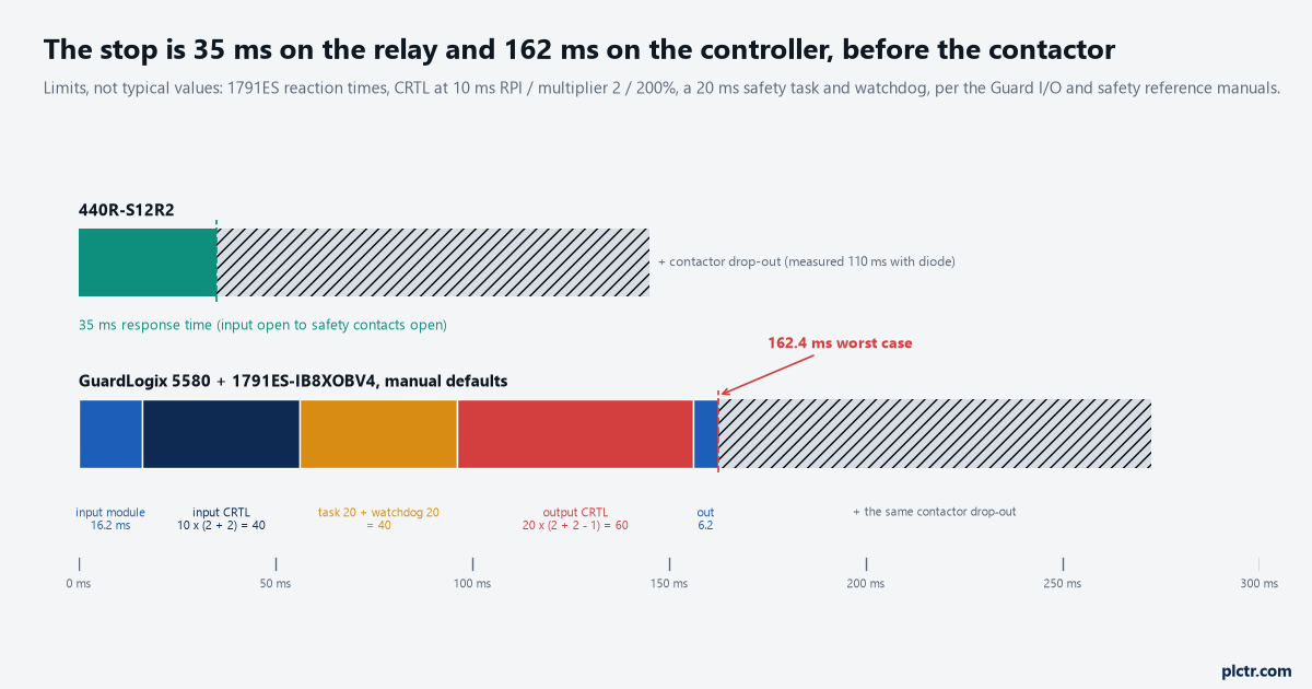
Worst-case limits from the safety reference manual’s defaults, not measured values. Whether 162 ms is a problem depends on the distance from the door to the hazard, and that number was set for 35.
Redo the distance arithmetic before the door goes back on. The relay’s 35 ms was in it.
What nothing on the controller replaces
The relay was replaced by whoever was on shift, against a drawing, in the time it takes to land fourteen wires; the module is not.
A spare Guard I/O module needs the safety network number written into it, the electronic keying has to accept its firmware, and the controller will not do either on its own once the project carries a safety signature – the procedure and its three ways of going wrong are the SNN and signature article. The functional test after the swap is the same on both boxes; the manuals say it every time and the relay’s manual said it too. The reset button, the switch, the contactors, the mirror contacts, the diodes across the coils: identical parts, identical wiring at the field end, and the risk assessment that put a Category 3 structure with two contactors on this door is not made better by the controller. What the controller gives you is not safety, it is the next function: the second guard, the E-stop that has to interlock with it, the muting on the infeed, and a fault code on the HMI instead of a flash count on a relay. That is the case for the move, and it is made properly in the relay-or-controller article. One door on its own never needed it.
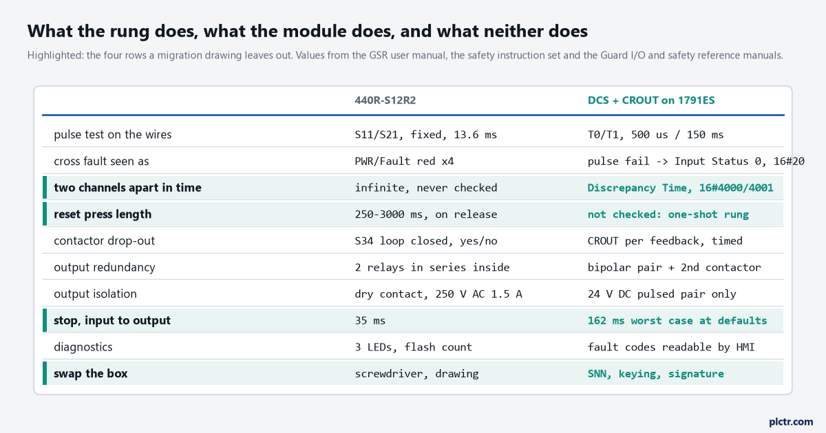
The four highlighted rows are the ones a migration drawing tends to leave out: the press check moves into a rung you write, the discrepancy check appears from nowhere, the response time quadruples, and the swap needs a laptop.
The thing everyone checks first
The switch, and it is never the switch.
A DCS that faults on the first close after a migration has the door opened and shut twenty times while somebody watches the two input LEDs, and then the switch is replaced with a new one that does exactly the same thing. Trend I0 and I1 at the safety task period across ten closes first; the gap between the two rising edges is the discrepancy this switch has always had, and the Discrepancy Time has to sit above the longest of them with margin. If the gap is under the setting and the fault is still there, look at the Test Source on each input, because I1 sourced from T0 by a slip of the dropdown fails its pulse test on every scan and reports through Input Status rather than as a discrepancy. Only then the switch.
Trend the two channels, then the test sources, then the switch.
Next step
Take the relay’s terminal list and write, against each terminal, the module point and the operand that took it: S11 and S21 to T0 and T1, S12 and S22 to I0 and I1 with their test sources, the S34 loop to three inputs and two instructions, 13/14 and 23/24 to O0 and O1, Y32 to a tag. Then measure the three numbers the relay never needed – the gap between the two channels on this switch, the drop-out of these contactors with the diodes fitted, and the reaction time chain with the CRTL values you actually configured – and put all three on the drawing. The safety function that spans two controllers, where this guard’s stop has to reach the conveyor upstream, is the next article, and it adds a connection with its own timeout arithmetic to the chain above. And when the same door comes up in a year with a spare module that will not connect, the answer is the SNN, not a download.
The rung replaced the decision. Everything the decision was about is still bolted to the door.