A 1734-AENT on a remote I/O rack stores its chassis size in non-volatile memory, and the user manual says in as many words that the chassis size setting is not communicated to the adapter during a connection request from the controller. Download a project with the new rack in it and the adapter you just wired still thinks it is a chassis of 1, makes no I/O connections, and puts a yellow triangle on every module under it. That is the fault everyone meets first, and it is the harmless one, because it belongs to the rack you added.
The fault that matters is on the rack that was working.
Three things do that: the download itself, a module slipped into the existing rack at the same time, and a second adapter brought up on the first one’s IP address. All three are avoidable, and on EtherNet/IP the whole job can be done with the controller in Run, provided you add the right things in the right order. The example here is a 1756-L83E with a 1756-EN2T, rack 1 a 1734-AENT with six modules, rack 2 a second 1734-AENT with four.
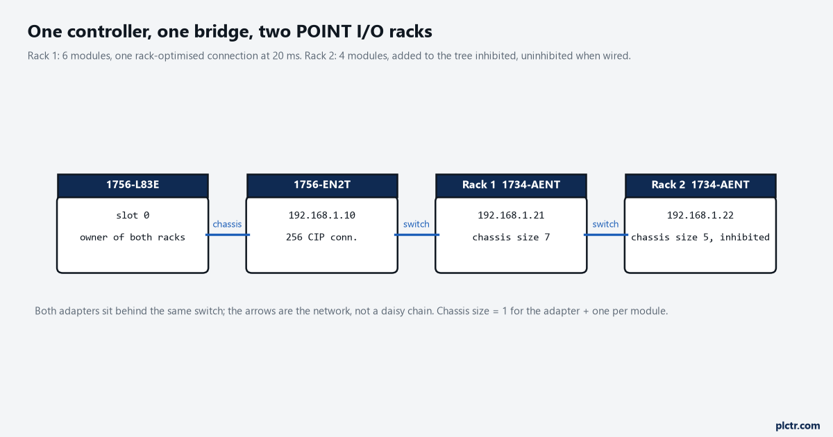
Rack 2 goes into the I/O tree with the Inhibit box ticked. The controller then makes no connection attempt to 192.168.1.22 until you clear it, and nothing about rack 1 changes when the entry appears.
Why rack 1 faults at all
Start with what a rack-optimised connection is, because it decides what can be added while the controller is running. The digital I/O manual describes it as one rack connection with a single RPI in place of several direct connections, with the input data limited to general faults and data. The design considerations manual adds the cost: 12 bytes of overhead per rack, 8 bytes per slot from the adapter to the controller and 4 bytes per slot back, sent for every slot whether it holds a module or not. Rack 1 is one such connection at 20 ms, plus nothing else, because all six modules are plain digital. Now the design considerations manual’s table of what can be added online. Via an EtherNet/IP network, a digital rack-optimised connection can be added offline and at runtime, a 1756-ENx adapter with a rack-optimised connection likewise, and a digital or analog direct connection likewise. The row for 1734 POINT I/O reads offline yes, runtime no. So a whole new adapter with its own rack connection goes in while running, and a new POINT I/O module inside an adapter that already has a rack connection does not.
That asymmetry is the entire method, and the table is worth printing out.
The download is the first way to fault rack 1. If rack 2 is added offline and downloaded, the controller goes to Program to accept it, and every output on rack 1 goes to its Program-mode state for as long as the download and the restart take. Nothing faults in the sense of a code, and everything stops.
The manual’s guidance for a plant that knows a rack is coming is to add it to the tree as rack-optimised in advance and inhibit the adapter until the chassis is needed, and that is the shape to copy even when the rack is coming next week rather than next year.
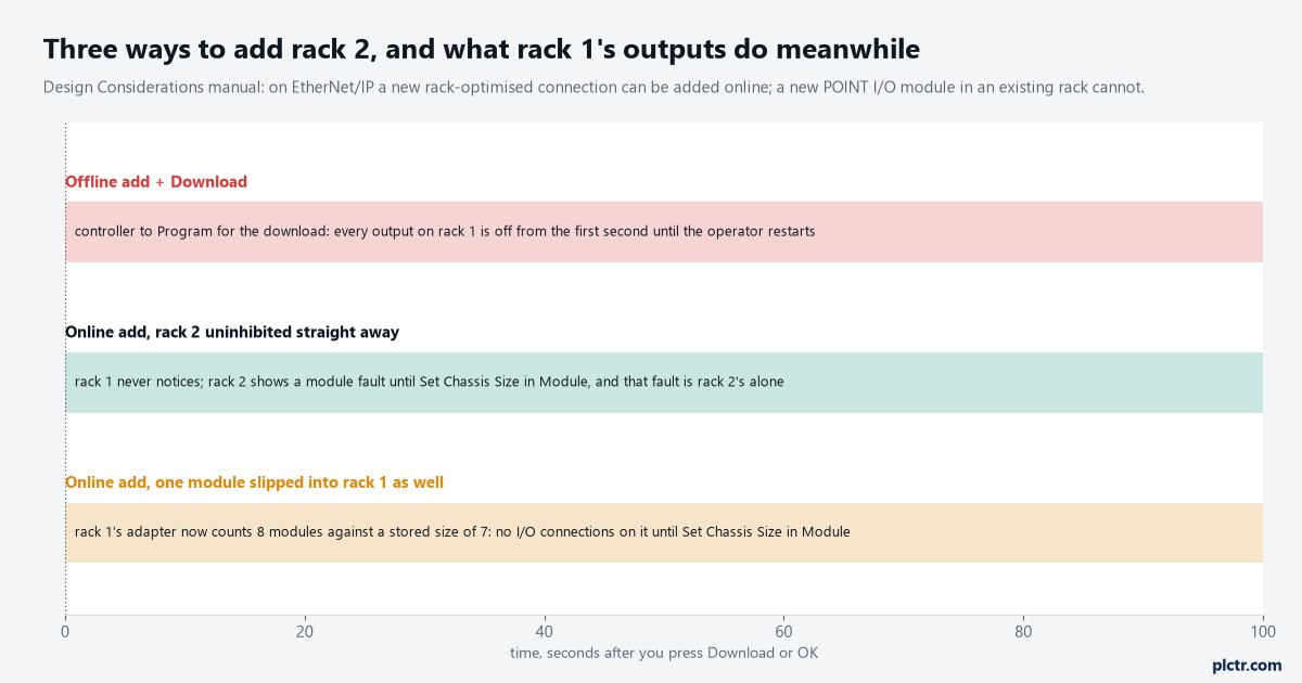
The middle line is the one to aim for. The bottom one is what happens when the second rack’s arrival is used as an excuse to add “just one more module” to the first.
The second way is that extra module. A POINT I/O adapter runs no I/O after a power cycle until the number of modules on its backplane equals the stored chassis size, and while running it cannot detect an empty terminal base at all, so it counts what answers. Add a 1734-IB8 on the end of rack 1 and the adapter has eight modules against a stored size of 7. No I/O connections, on that adapter, for every module, until somebody goes to the adapter’s Chassis Size tab and presses Set Chassis Size in Module. The manual’s own procedure for that is done online and shows the value from the software next to the value stored in the adapter; it is a separate, deliberate operation, and it always was. The third way is the address. A second adapter set up from the same BOOTP session or the same sticky note as the first comes up on 192.168.1.21. The EtherNet/IP devices manual describes duplicate IP address detection running when a device connects or its address changes: the port transitions to conflict mode, the OK indicator blinks red, the NET indicator goes steady red, and a device with a text display scrolls its own address, the words Duplicate IP, and the MAC of the other node. The manual does not promise which of the two ends up in conflict mode, so plan not to find out. Set 192.168.1.22 on the bench, on its own, before rack 2 sees the plant switch.
One address per adapter, written on the door, before the second one is powered.
The order that adds a remote I/O rack without faulting the first
Rack 1 stays in Run through all of this, and nobody touches it.
- Offline, or online with the controller in Run, add the second 1734-AENT under the 1756-EN2T. Name it, give it 192.168.1.22, choose Rack Optimization as the Comm Format, set Chassis Size to 5, and tick Inhibit Module on the Connection tab. If you are online, the adapter appears in the tree and the controller does nothing else.
- Add the four modules under it, each with Rack Optimization as its connection. The 1734-AENT manual says the New Module entry goes dim once you have added as many modules as the chassis size allows, which is a useful check that the 5 is right.
- Wire rack 2. Power it. Set its IP address with it connected only to the laptop, then move it to the plant switch.
- Online, open rack 2’s adapter, go to the Chassis Size tab, press Set Chassis Size in Module, and acknowledge the warning. The stored value changes from 1 to 5.
- Clear Inhibit Module. The rack connection opens, the POINTBus indicator on the adapter goes solid green, and the yellow triangles on rack 2 clear. Rack 1’s adapter, its modules and its connection tab have not changed at any point.
The digital I/O manual carries one rule that trips people at step 2: the adapter and the modules under it have to agree. If the adapter is rack-optimised and a module is configured for a direct connection, or the other way round, the controller makes two connections to the same chassis and sends the same data twice. Diagnostic and fused output modules are the exception the manual names, because their extra data does not travel over a rack connection and they need a direct one anyway; the 1734-AENT manual’s floors are an RPI no lower than 10 ms for a rack connection and 50 ms for a direct one, to avoid overloading the adapter.
The dead end: replacing the adapter
When rack 2 sits there with a module fault after step 3, the adapter gets blamed. A spare 1734-AENT goes on, the same fault appears, and now two adapters are suspected. The manual has a paragraph headed Adapter Replacement that says exactly why: the chassis size is not communicated during a connection request, this includes situations when you are replacing an adapter, and the adapter does not make any I/O connections until it is configured with the appropriate chassis size. The first adapter was fine. So is the second.
Both are chassis size 1, and both were when they left the box.
Write the chassis size on the inside of the panel door next to the IP address. The next person to replace that adapter at 3 am has a laptop and no idea the Chassis Size tab exists.
The budget rack 2 is spending
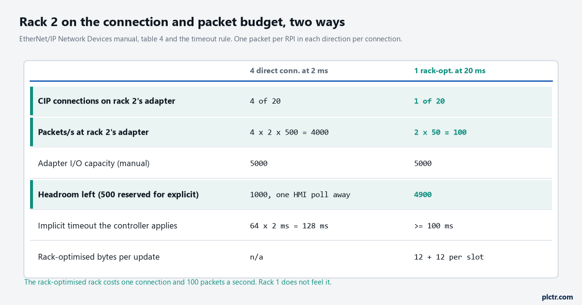
Each I/O connection sends one packet per RPI in each direction. Four modules at 2 ms is 4000 packets a second at an adapter the manual rates at 5000, before any explicit messaging.
This is where the first rack can be hurt without anyone touching it, and it is arithmetic rather than a setting. The EtherNet/IP devices manual rates a 1734-AENT at 20 CIP connections and 5000 I/O packets per second, and asks that 10% of a device’s packet rate be reserved for temporary explicit messaging.
Then it gives the rule that decides when a late packet becomes a fault.
An implicit connection is declared lost after a multiplier times the RPI, chosen so the timeout is at least 100 ms, with the examples 2 ms and 64 for 128 ms and 10 ms and 16 for 160 ms. Rack 2 as one rack-optimised connection at 20 ms is 100 packets a second and one connection, and the 1756-EN2T, at 256 CIP connections, does not notice. Rack 2 configured as four direct connections at a 2 ms RPI, which somebody will try because the new modules are “fast inputs”, is 4000 packets a second on the new adapter and 4000 more through the EN2T, whose packet rate the manual says depends on series and firmware revision and does not print in the table. Rack 1’s 100 packets a second are now queued behind that, and a rack connection that misses its window for the multiplier’s worth of RPIs — at least 100 ms, by the manual’s rule — is a timeout and a fault on a rack nobody changed. The fix is not on rack 1, and it never was.
It is the RPI on rack 2, back to the manual’s 10 ms floor for a rack connection or 50 ms for a direct one, and a look at whether a 2 ms input scan was ever going to be honoured by an adapter rated at 5000 packets a second in total. The wider connection accounting, including what a produced tag costs against the same pool, is in EtherNet/IP PLC communication: setup, RPI and faults.
What Compact 5000 and 1756 remote chassis do differently
Two footnotes from the design considerations table, for the next rack rather than this one. Compact 5000 I/O does not support rack optimisation at all, every 5069 module is a direct connection, and the online-addition row for it says runtime addition is only supported if adding an entire rack of Compact 5000 I/O modules — so a 5069-AEN2TR with its modules goes in as a unit, and a single module added to an existing 5069 rack is an offline job. A 1756 remote chassis behind a second 1756-EN2T is the most forgiving case: the table allows both the adapter’s rack-optimised connection and individual digital or analog direct connections at runtime, and the design consideration is simply to leave empty slots in the chassis for what is coming.
Leave the slots. Empty slots cost nothing and a download costs a shift.
What to check next
Before touching the tree, open rack 1’s adapter online and write down three numbers: the Comm Format, the RPI on the Connection tab, and the chassis size the adapter reports on its Chassis Size tab. Those are the three that must be the same afterwards. Then set rack 2’s address on the bench, add it inhibited, set its chassis size in the module before you uninhibit, and read the module fault text on the Connection tab rather than guessing at the triangle. If the problem is not the rack but the bridge in front of it, the catalogue-module version of this job is in adding a new module with Logix Designer and the generic-profile version in a generic EtherNet/IP module: connection parameters and RPI. And if rack 1 faulted anyway, the code on its Connection tab is the place to start, read against Allen-Bradley PLC I/O faults, causes and solutions.