A 1769-IQ16 has a published input delay of 8 ms on and 8 ms off. A 1024 PPR encoder on a shaft turning at 600 rpm produces 10,240 pulses every second, which is one edge pair every 97.7 microseconds, and the card’s own filter is eighty times longer than the whole pulse. That is why an encoder lands on a high speed counter input instead.
It will not miss some of them. It will see essentially none of them.
That number is the entire reason high speed counter hardware exists, and it is worth having in your head before the argument starts, because somebody will always suggest trying it on a spare input first.
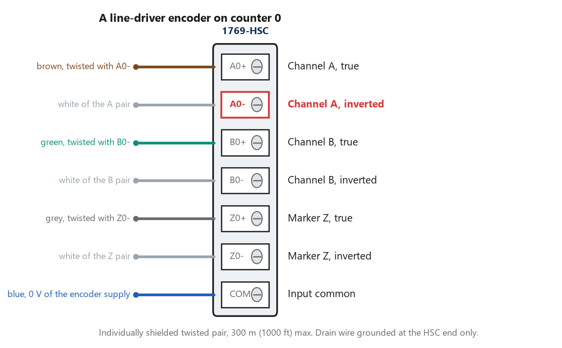
Six signal terminals per pair of counters, two per channel. A0- is highlighted because it is the terminal people leave empty, and what happens next depends on which kind of encoder you bought.
Why the ordinary card cannot do it, in two separate ways
The input delay is the first reason and the easy one. 1769-TD006H puts the plain 1769-IQ16 and 1769-IQ32 at 8 ms on and 8 ms off, which is a fixed hardware filter rather than a setting, and it exists to stop a bouncing contact producing four inputs. It works, and it is exactly wrong for an encoder.
The 1769-IQ16F variant does give you a selectable digital filter with a much shorter minimum, which narrows the gap without closing it, and it leaves the second reason completely untouched. That second reason is the one that survives after somebody finds a card fast enough. A standard input is read once per I/O update and evaluated once per program scan, and those two events are not synchronised with each other. Even if the card could resolve a 97 microsecond pulse, your logic sees a snapshot of the input’s state, not a count of how many times it changed since the last snapshot. Between two scans the encoder could have produced forty transitions and the bit you read is simply high or low. Counting transitions in ladder works when the thing you are counting is slower than your scan by a wide margin — a part crossing a photo eye, a bucket passing a proximity switch — and stops working the moment it is not. That distinction is why timer and counter instructions and a counter module are answers to different questions.
A counter module moves the counting into hardware that never sleeps, and hands your program a number instead of a bit.
What a high speed counter input actually gives you
The 1769-HSC has six high-speed differential inputs, labelled ±A0, ±B0, ±Z0, ±A1, ±B1 and ±Z1. That supports two quadrature encoders with ABZ inputs, or up to four discrete count inputs, and x1, x2 and x4 encoder configurations are provided. Inputs are optically isolated from the bus and from one another, and have an operational range of 2.6 to 30V DC.
Maximum count rate then depends on what you asked it to do, and the spread is wide.
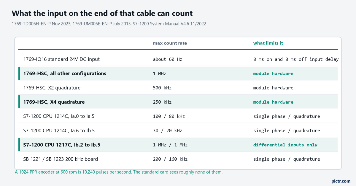
Three of these rows are on the same physical CPU. Which S7-1200 terminal the A channel lands on changes the answer by a factor of four, and nothing on the terminal marking tells you.
That middle block of rows deserves saying twice.
It looks like a wiring decision and it is a specification decision. On a CPU 1214C or 1215C, inputs Ia.0 to Ia.5 count at 100 kHz single phase and 80 kHz in quadrature. Inputs Ia.6 to Ib.5 on the same CPU count at 30 kHz and 20 kHz. An electrician landing the A channel on Ia.7 because it was the next free terminal has quietly cut your ceiling by three quarters, and the failure will not be a fault light. It will be a position that drifts under acceleration. The 1217C is the interesting one in that family. It carries four genuine differential inputs at Ib.2 to Ib.5, with 220 ohm termination and bias built in, and those run at 1 MHz single phase and 1 MHz in quadrature. Every other input on every other S7-1200 is single-ended 24 V. Siemens keeps the two kinds on separate terminal groups; Rockwell puts both on the same terminals and lets you choose. Both approaches are defensible and they fail differently, which matters when you are reading somebody else’s drawing.
Two channels, and what x4 is buying
A single channel tells you that something moved.
A and B together tell you which way, and that is the whole of what quadrature buys before you get to resolution.
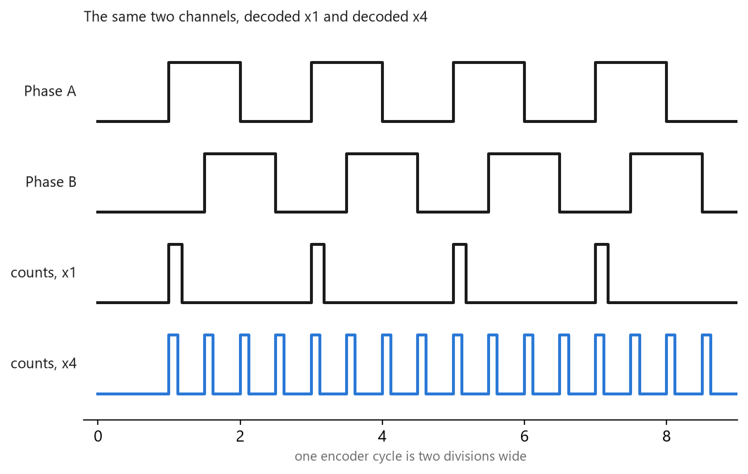
The four x4 counts come from the rising and falling edge of both channels. Nothing about the encoder changed between the two bottom traces, only the decoding.
Siemens prints the edge logic out longhand and it is worth reading once. Its plain A/B counter counts up on the rising edge of clock A when clock B is low, and down on the falling edge of A when B is low. Its A/B counter fourfold lists all eight conditions, up and down on both edges of both channels, and that is where the multiplication comes from. Rockwell calls the same thing x1, x2 and x4 and draws the waveforms instead.
Resolution is the point, and it is free in the sense that you buy no extra hardware, at a cost you should notice: on a 1769-HSC, x4 quadrature tops out at 250 kHz while every other configuration runs to 1 MHz. You are trading count rate for resolution, four to one, and on a fast shaft that trade can be the wrong way round. Which brings in the arithmetic the mechanical side hands you, and this is really where the encoder gets chosen rather than in a catalogue. Say the encoder is 1024 PPR on a drive roller of 200 mm diameter. The roller circumference is 628.3 mm. In x4 that is 4096 counts per revolution, so one count is 628.3 / 4096 = 0.153 mm of belt. Run the belt at 1.5 m/s and the roller turns 2.39 times a second, which is 9,780 counts per second. Comfortable on anything in the table above.
Then somebody mentions the gearbox.
Mount the encoder on the motor rather than the roller, behind a 3.2:1 reduction, and the encoder now turns 7.64 times a second. Your resolution improves to 0.048 mm per count, which nobody asked for, and your count rate goes to 31,300 per second, which lands you above the 30 kHz single-phase ceiling of an S7-1200’s Ia.6 to Ib.5 group and above the 20 kHz quadrature ceiling comfortably. Same encoder, same belt, same CPU, and the answer changed because of where it was bolted.
Work the count rate out at maximum line speed rather than at normal line speed.
A threading or jog speed is often faster than production, and it is the one nobody puts on the spec sheet.
Where the pulses actually go missing
Three things, in the order they happen on a job.
The cable. 1769-UM006 is specific: shielded cable is required for the high-speed input signals A, B and Z, using individually shielded twisted-pair cable for lengths up to 300 m. Individually shielded means each pair gets its own shield rather than one foil around the lot. Siemens is far tighter on length for its onboard counters and publishes 500 m shielded and 300 m unshielded for general digital inputs, then 50 m shielded specifically for HSC inputs. Fifty metres. If you are running an encoder back to a CPU across a large machine, that number decides where the CPU goes.
The shield, and here the two vendors disagree in print. Rockwell says to ground the shield drain wire at the 1769-HSC module, input end only, and the installation steps have you cut back and insulate the drain at the encoder. Siemens, in its wiring guidelines, says that when using shielded cables you should always connect the cable shields to ground at both ends to reduce low and high frequency interference. Those are genuinely opposite instructions and both are printed by the vendor whose hardware you are wiring to. Follow the one that matches your module. What you must not do is average them, or do one on Monday and the other on Tuesday, because a shield grounded at both ends between two points at different potentials becomes a conductor with current in it, and a shield grounded at neither end is decoration.
The encoder’s output type, which is the expensive one. The 1769-HSC accepts standard differential line driver devices and single-ended devices such as limit switches, photo eyes and proximity sensors, on the same terminals. That flexibility is the trap. A single-ended device needs a pull-up resistor if one is not already inside it, and the manual makes you calculate it rather than fitting it for you.
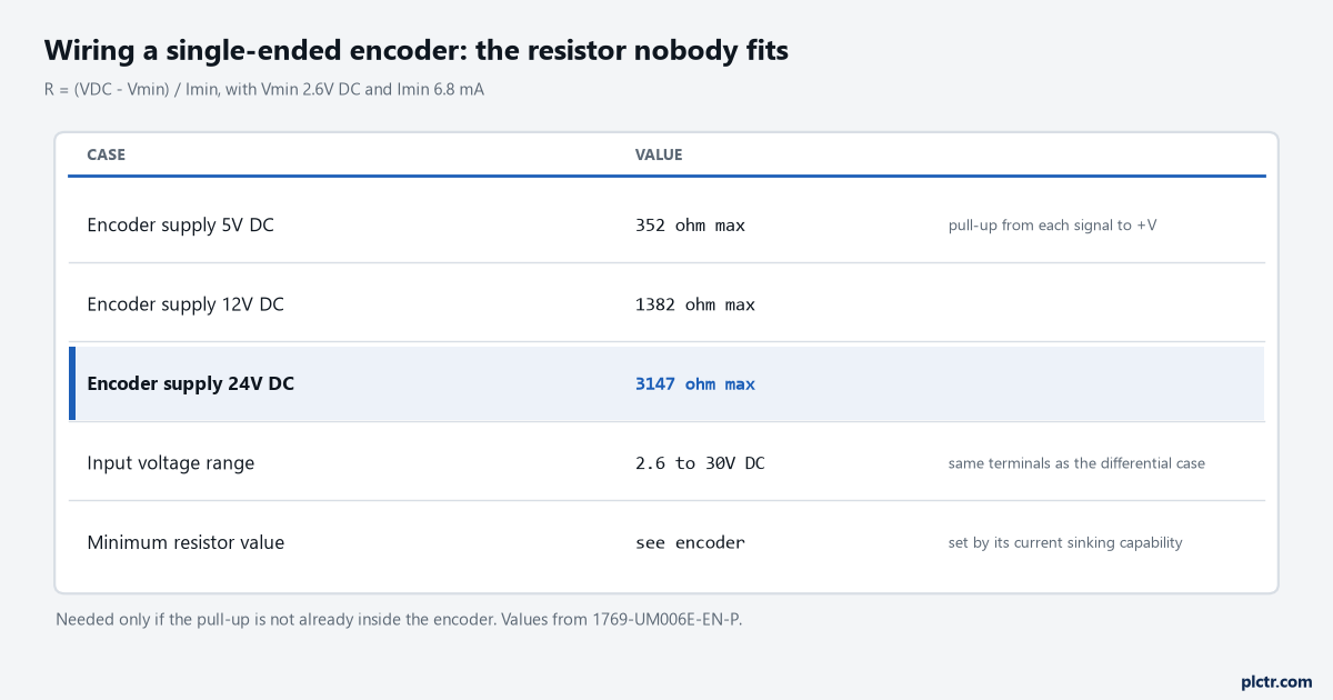
The formula is the module’s own. Vmin is 2.6V and Imin is 6.8 mA, which is what the input needs to see before it will call a signal true.
The symptom of getting this wrong is not a dead channel. It is a channel that counts at low speed on the bench and loses counts under load, because without the pull-up the signal’s rising edge is slow and the module is timing that edge against a threshold.
Which brings us to a differential encoder half-wired.
Land A0+ and leave A0- empty and you have not made a differential encoder into a single-ended one. You have left a receiver looking at one leg of a pair whose other leg is being actively driven somewhere else, with nothing defining the reference. Sometimes it works on the bench, at 300 rpm, on two metres of cable, which is exactly why it gets signed off. Then the VFD starts, the common-mode noise that the differential pair existed to reject arrives on the single leg you kept, and the count wanders. To be straight about the evidence: 1769-UM006 publishes wiring diagrams for both the differential and the single-ended case and does not print an explicit prohibition on half-wiring a differential device. What it does print, under its noise guidance, is the recommendation to use devices which output differential signals, such as differential encoders, to minimize the possibility that a noise source will cause a false input. The manual’s argument for the pair is noise immunity. Discard half the pair and you have discarded the reason it was specified.
The same section is worth taking seriously on routing generally. Group the module away from AC and high voltage DC modules, keep field wiring away from motors, transformers and contactors, and where a field wire must cross a power cable, cross it at right angles. None of that is new and all of it is in the manual with the module’s name on it, which is a more useful thing to put in front of a panel builder than a general principle.
What to check next
Put the raw count on a trend and turn the shaft by hand, one revolution, slowly. The count should change by exactly the counts per revolution you calculated, and if it changes by a quarter or four times that, your x1, x2 and x4 setting disagrees with your arithmetic rather than anything being broken. Then do it again at full speed and compare the delta over a known distance: a count that is right at walking pace and low at line speed is a signal integrity problem and the cable is where you start, not the configuration. If the module itself is not in the tree yet, that is a separate job and adding a new module in Logix Designer covers it. If you are still choosing the encoder, what an encoder is and where they get used covers the incremental and absolute decision that sits upstream of all of this, and the sinking and sourcing question that decides whether a single-ended device will drive your input at all is worked through in matching a PNP sensor to the input card you have. Where the counts are feeding a position rather than a speed, Logix motion control is the other road out of here.