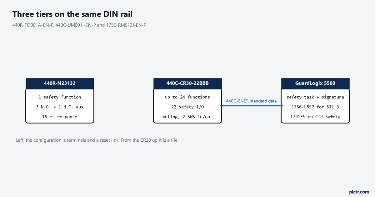
A 440R-N23132 watches one guard switch, opens three N.O. safety contacts in 15 ms, and the whole of its configuration is which terminals you land wires on and whether you fit a link across the reset loop. A 440C-CR30-22BBB holds up to 24 safety monitoring functions on 22 safety-rated terminals, and its configuration is a file on somebody’s laptop. Both of those are the right answer on some machine. Safety relay vs PLC is not settled by how dangerous the machine is. Count the safety functions. One guard, one E-stop circuit, one contactor pair, nobody asking for diagnostics: the relay wins and it is not close. Three or four functions that have to interlock with each other, or one that needs muting, or a maintenance department that wants to know on the HMI which of six gates is open, and you have crossed over. Everything below is where that line sits and what it costs you on each side of it.
Parts named here are Rockwell, because Rockwell’s safety literature is what these figures trace to.
What a relay is genuinely good at
Nothing about it can be configured wrong from a keyboard.
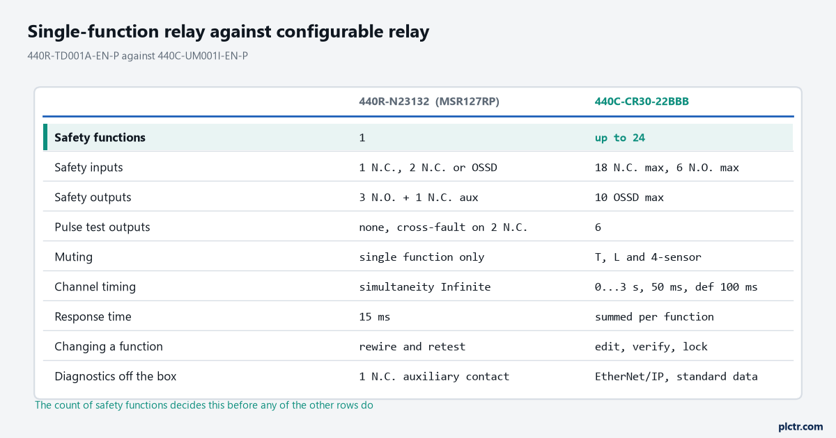
Take the MSR127RP, 440R-N23132 in the 24V DC removable-terminal version. 440R-TD001A gives it one N.C., two N.C. or OSSD inputs, three N.O. safety contacts and one N.C. auxiliary, a 15 ms response time, 1 second power-on delay and 100 ms recovery, cross-fault monitoring when it is connected as two N.C. inputs, and a mechanical life of 2,000,000 operations across -5…+55 °C. The datasheet also gives it a PFHd below 1.45 × 10⁻⁹ and an MTTFd above 398 years, on the stated assumptions of a 20-year mission time and a functional test at least once in any six-month period. It lists the unit as Cat. 4 PLe per ISO 13849-1 and SIL 3 per IEC 61508 and IEC 62061, TÜV certified. That listing is Rockwell’s statement about its own product from its own technical data; ISO 13849-1 and IEC 61508 are not reproduced here, and neither number belongs to your machine until somebody has evaluated the whole function, sensor through logic to contactor.
What you get for that is a box with no firmware revision, no project file, no signature and no password.
That matters at 02:00. A relay that has failed gets swapped by whoever is on shift, against a drawing, with a screwdriver. There is no laptop, no software version to match, no download, no configuration to re-verify before the line runs. Compare that with replacing a safety module on a networked system, where 1791ES-UM001H has the controller checking the IP address and the safety network number and the configuration signature before it will hand the module its configuration, and getting any of those wrong leaves you with a module that is present, healthy and refusing to come online. That is a solvable problem and it is a problem the relay does not have.
One more thing the relay does that people misread as a limitation.
Look up input simultaneity in 440R-TD001A and the MSR127RP says Infinite (ch2 before ch1) with Auto Reset. The MSR126R/T, MSR131RTP and several others say Infinite outright. The relay is not policing how far apart your two channels change state, which sounds like a gap until you notice that this is precisely the setting people get wrong on a safety controller – see discrepancy time on a dual-channel safety input for what that number is and what happens when it is guessed. Where a relay does police simultaneity, the number is fixed and comes from the application: the MSR125H two-hand control unit requires both switches within 0.5 seconds of each other, and 440R-TD001A ties that to ISO 13851 Type IIIC, a standard I have not read and am quoting the datasheet’s reference to.
Where the relay stops being cheap
It stops when you start counting relays.
A single-function safety relay does one safety function. That is not a criticism, it is the category name in Rockwell’s own technical data – MSR117T, MSR126R/T, MSR127RP/TP and MSR131RTP are all listed as single-function safety relays. Two guards and an E-stop is three relays. Add a delayed stop for a spindle that has to coast and you are into an MSR138DP or a CU4 off-delay unit. Run out of contacts and you add an MSR132E expansion relay. Each of those is another 22.5 or 45 mm of DIN rail, another set of terminations, another page of the drawing, and another interlock between units that somebody has to wire and somebody else has to understand two years later.
The cost is never the relay. It is the terminations and the drawing.
And then the change request arrives. Zone 2 now has to stay running when zone 3 stops, the loading door needs a different behaviour in manual mode, and the pallet has to go through the light curtain without stopping the conveyor. In relays, every one of those is a wiring change inside a live panel, a mark-up on the drawing, and a full re-test of the functions you disturbed on the way past. In a configurable box, two of the three are edits and the third might already be a block.
The box in the middle that gets skipped
Most of the arguments about relays against safety PLCs are really arguments about the thing between them.
The Guardmaster 440C-CR30-22BBB is a software configurable safety relay built on the Micro800 platform, red housing so nobody mistakes it for a standard controller. 440C-UM001I gives it 22 embedded safety-rated inputs and outputs and up to 24 safety monitoring functions, with a maximum of 18 N.C. safety inputs, 6 N.O. safety inputs, 6 pulse test outputs and 10 OSSD safety outputs, plus two plug-in slots carrying four standard inputs and four standard outputs each. Configuration is in Connected Components Workbench, which is free. Muting is in the box: three types, 2-sensor T, 2-sensor L and 4-sensor, needing three consecutive unassigned safety monitoring blocks. Each two-input function has its own discrepancy time, 0…3 seconds in 50 ms increments with a default of 2, which the manual spells out as 2 × 50 = 100 ms.
For a great many machines that is the whole answer, and it costs one part number.
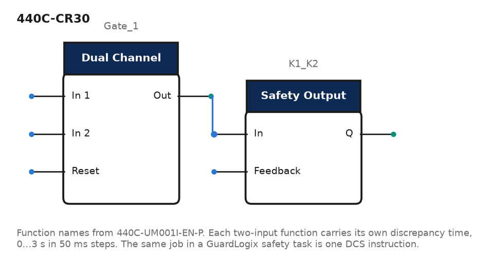
It is also where the honest warning belongs, because a configurable box is configurable in both directions. The same manual says that if the discrepancy time is set to 0, the discrepancy test does not occur. A check people assume is welded into the hardware is a value in a configuration file with a legal setting that turns it off. The relay cannot be mis-configured because there is nothing to configure; from the CR30 upwards, somebody can, and the verification and lock steps in the CR30’s own workflow exist for exactly that reason.
Safety relay vs PLC: when it has to be the controller
Four things push you past the configurable relay, and only one of them is about counting.
The first is scale and reach – safety functions spread across chassis, across a line, or across more I/O than one box has terminals, where the CIP Safety connection to a 1791ES drop replaces a trunk of hard wiring. The second is that the safety function has to know something the standard program knows: a recipe, a mode, an axis position, a state machine that already lives in the controller. The third is diagnostics as a deliverable, where the maintenance HMI has to name the gate and the operator has to be told which of eleven interlocks dropped the cell. The fourth is a safety function that has to be produced and consumed between two controllers, which no relay does at all.
On the Rockwell side that means a GuardLogix 5580 or a Compact GuardLogix 5380, and 1756-RM012J is specific about what the catalogue number buys. A GuardLogix 5580 with only the primary controller is rated SIL 2, SIL CL 2, PLd (Cat. 3); add the 1756-L8SP safety partner and it is SIL 3, SIL CL 3, PLe (Cat. 4). On Compact GuardLogix the digit is in the part number – a 5069-L3xxxxxS2 is the SIL 2 / PLd rating and a 5069-L3xxxxxS3 is SIL 3 / PLe. Those ratings are the manual’s, expressed against ISO 13849-1 and IEC 61508, neither of which is reproduced here. Two more lines from the same manual are worth pinning to the wall: only the safety task, not standard tasks, can be used for safety functions, and the safety signature is required for the controller to operate at a SIL 2 or SIL 3 rating, with operation without a signature suitable only during development.
That last one is the real cost of the controller, and it is not the hardware.
A signature means a frozen, verified safety program. Changing one rung means deleting the signature, making the edit, generating a new one and re-validating the functions the edit touched, with a record of all of it. That is the right amount of ceremony for a machine with eleven interlocks and a robot. It is a ridiculous amount of ceremony for a guillotine with one gate, and a site that specifies a GuardLogix for the guillotine has bought itself a change-control process it will resent for the next decade. The logic itself is not the hard part; the instruction set is small and readable, and the safety instruction set and its reset parameters covers DCS, DCST and their relatives, with the dual-channel E-stop worked end to end as the example.
What changes when safety has to talk on a network
A wire either has 24V on it or it does not.
A safety connection also has to prove the data on it is fresh.
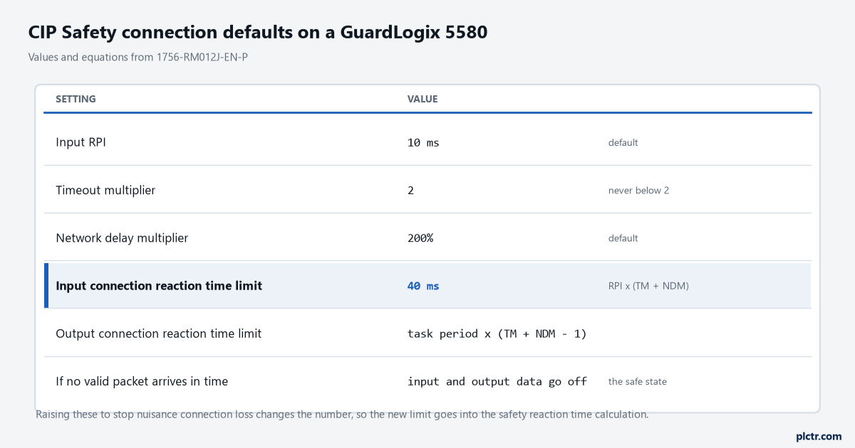
CIP Safety does that with a connection reaction time limit, and 1756-RM012J gives the arithmetic and the defaults plainly. Input connection reaction time limit is the input RPI multiplied by the timeout multiplier plus the network delay multiplier; the output limit is the safety task period multiplied by the same sum less one. Defaults are a 10 ms input RPI, a timeout multiplier of 2 and a network delay multiplier of 200%, which produces a 40 ms input connection reaction time limit. If a valid packet does not arrive inside that window the connection times out and the input and output data go to the safe state, off. The manual carries two warnings next to those numbers: never set the timeout multiplier below 2, and for applications with safety I/O the default limit can cause connection loss, so the values sometimes have to go up – and when they do, the new figure has to go into the safety reaction time calculation rather than being left as a number somebody adjusted to stop the nuisance trips.
Forty milliseconds of default staleness allowance is a design input, not a network setting.
The configurable relay meets the network at a different place and it is worth being precise about. With a 440C-ENET plug-in module the CR30 appears in the Logix I/O tree under an Add-On Profile and exchanges I/O and explicit messages with a ControlLogix or CompactLogix – which 440C-UM001I describes as reading and writing I/O data for diagnostics and control. That is standard data on a standard connection. When an actual safety state has to cross from the CR30 into another safety device, it goes on a wire as single wire safety: a long pulse followed by a short one, 4 ms and 1 ms at 24V, repeated while the signal is active, 0V when it is not, on terminals 10 and 11 for an input and up to two outputs going the other way. So the CR30 gives you the diagnostics on Ethernet and keeps the safety signal on copper, which for a cell with one HMI and one machine is often exactly the right split.
Where the Siemens parts land
Same three tiers, different labels.
The single-function relay tier is SIRIUS 3SK1. The configurable tier is the 3RK3 modular safety system. The controller tier is an S7-1500F or an ET 200SP distributed F-CPU with F-DI and F-DQ modules, talking PROFIsafe rather than CIP Safety, with an F-destination address on each module playing a role close to the safety network number. The selection argument transfers without change: count the safety functions, ask whether any needs muting or zoning, ask who needs the diagnostics, ask whether a safety state has to cross between controllers. What does not transfer is the numbers, and I am not going to pretend otherwise. Every figure in this article traces to a Rockwell publication that was open while it was written, and no Siemens safety manual was. When this site covers the Siemens side – passivation and reintegration on an F-module, and setting up an ET 200SP F-DI – it will be from the Siemens documentation, with the response times and ranges taken from there.
The case for the relay, said plainly
If a site always recommends the bigger box, it is selling, not advising.
Here is the honest version. If the machine has one or two safety functions, if those functions do not have to know anything about each other, if nothing needs muting or a mode switch or zoning, if the diagnostics requirement is satisfied by a lamp and an auxiliary contact, and if the people who maintain it are electricians rather than programmers, then a 440R relay is not the compromise choice. It is the better engineering: fewer failure modes, no software configuration to be wrong, no signature to manage, no laptop needed to put the machine back in service, and a device whose entire behaviour is visible on one page of a drawing. The safety controller buys flexibility, and flexibility is a cost until you need it.
The cost shows up as change control, not as hardware.
Next
Before anything else, write down the safety functions as a numbered list with the devices on each one, because that list decides this and almost nothing else does. Then mark which of them needs muting, which needs to know a machine mode, and which has to be reported somewhere a person can read it. If the list is one or two lines and the marks are empty, buy the relay and put the difference into better guarding. If it is six lines with three marks, the configurable relay is probably the answer and the safety controller is the answer only when the reach or the produced-and-consumed requirement forces it. Either way, the reaction time and the architecture come next, and risk assessment through to a PL d architecture is where that work starts.