A PowerFlex 525 F059 Safety Open means S1 and S2 are both sitting at zero volts.
Rockwell’s action line for the fault runs to two clauses: check the safety input signals, and where the drive carries no safety function, make sure the protective jumper across those terminals is present and tight.
That second clause is the one to be careful with, because the jumper that is the documented configuration on one machine is the thing defeating the protective device on the next. The drive leaves the factory with that jumper fitted. Removing it is the step that turns the terminals into working safety inputs.
So a new 525 that faults F059 out of the box, with nothing landed on the safety terminals, is a drive whose jumper is missing.
Everything below is from publication 520-UM001O-EN-E, September 2025, which is where the safe torque off material now lives.
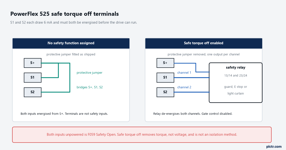
The three terminals and the two legitimate ways to leave them. S+ is internally tied to the drive’s own +24V, and each safety input draws 6 mA.
What Rockwell actually prints for PowerFlex 525 F059
The fault table entry is short enough to quote whole. Number F059, name Safety Open, type 1. Description: “Both of the safety inputs (Safety 1, Safety 2) are not enabled. Configure with t105 [Safety Open En].” Action: “Check safety input signals. If not using safety, verify and tighten jumper for I/O terminals S1, S2, and S+.”
Two things in there are easy to read past.
The word is both. F059 is the state where neither channel is energised, and one channel dropping on its own gets a different code.
And the fault is type 1, which on a 520-series drive means Auto-Reset/Run: if A541 [Auto Rstrt Tries] is non-zero, the drive will try to reset it on the A542 [Auto Rstrt Delay] timer. It will not succeed while the channels are still open, because the code reports a hardware state rather than a stored condition. That is why clearing it and cycling power twice changes nothing, which is where most of the wasted hours on this fault go. Terminal side, from the control I/O designations: S1 is Safety 1 and S2 is Safety 2, each drawing 6 mA, while S+ is Safety +24V, the “+24V supply for safety circuit”, internally tied to the drive’s own +24V. Under normal operation both inputs are energised and the drive is able to run. De-energise either one and the gate control circuit is disabled, blocking the gate-firing signals from reaching the output IGBTs.
Not the DC bus. Not the output terminals. The gate signals.
Why it is sometimes F111 instead
This is the part the fault table alone will not tell you, and it is worth knowing before you start pulling wires.
The two channels are watched against each other over a discrepancy window. Drop S1, and what happens next depends on whether S2 follows inside that window. If S2 follows in time, you get F059 Safety Open. If S2 never follows, the drive calls it F111 Safety Hardware, described as “Safety input enable hardware malfunction. One of the safety inputs is not enabled.” The window is firmware dependent, and the numbers are printed: one second on PowerFlex 525 FRN 5.xxx and later, ten milliseconds on FRN 4.xxx and earlier. A drive on old firmware is far quicker to call a sloppy relay contact a hardware fault than a drive on current firmware is, which is worth knowing before you conclude the control module has failed. F111 is also a type 2 fault rather than a type 1, and on FRN 5.xxx and later t106 [SafetyFlt RstCfg] decides how it clears: 0 “PwrCycleRset” is the default and needs a power cycle, 1 “FltClr Reset” lets it clear without one. Separately from the discrepancy window, the safety reaction time, measured from the input condition that triggers a safe stop to the initiation of safe torque off, is 100 ms maximum.
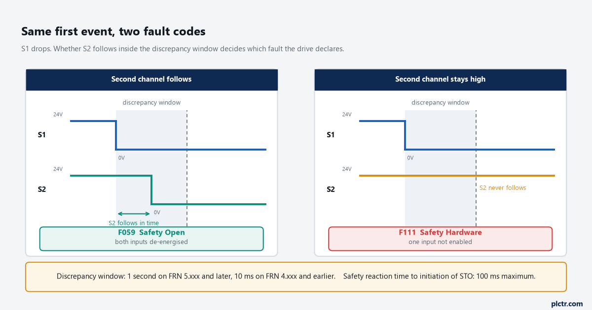
Same first event, two different fault codes. What separates them is whether the second channel follows within the discrepancy time, which is one second on FRN 5.xxx and ten milliseconds on FRN 4.xxx.
Getting to the terminal block
Note the code before you clear it.
The last three are held in b007, b008 and b009 [Fault 1…3 Code] in the Basic Display group, b007 being the most recent, and the range runs F0 to F127. A cleared display is worth less than knowing what the drive saw.
Then the dead work. Rockwell’s precaution is specific about the wait and the measurement: after power is removed, wait three minutes for the DC bus capacitors to discharge, then verify AC voltage at L1, L2 and L3 line to line and line to ground, and measure DC across the DC- and DC+ terminals to confirm the bus has reached zero. Keep the meter on the terminals until it reads zero, because the discharge can take several minutes. The manual adds the line that catches people out: darkened display LEDs are not an indication that the capacitors have discharged to a safe level. Lock out and tag out to ANSI/NFPA 70E is what the appendix calls for, not a habit anyone invented locally.
With the cover off, you are looking at three terminals and what is or is not bridging them. A missing jumper, a jumper present but loose in the clamp, a wire pushed out and lying against the insulation: those account for most of it, and all of them are visible without a meter.
Check what the schematic says belongs there rather than copying what the old drive had. The old drive is evidence, not authority.
When the jumper is the documented answer, and when it has to come out
Rockwell documents both states plainly, and the distinction is the whole safety question on this drive.
Jumper fitted. This is the shipped condition, and the one the manual’s basic operation test assumes: step 2 of that test is “Verify safety terminals (S1, S2, and S+) jumper is in place and tightened.” The fault action for F059 says the same for the case where you are not using safety. With the jumper in, both inputs are permanently energised from the drive’s own +24V.
Jumper removed. The procedure for enabling safe torque off is four steps: remove all power, confirm the bus voltage is zero, loosen the three terminal screws, take the protective jumper out. Step four is the sentence that matters. “The Safe Torque Off function is now enabled and the terminals are ready to function as safety inputs.”
Read those two together and the consequence is not a matter of opinion. While the protective jumper is fitted, the terminals are not functioning as safety inputs, so a guard switch, light curtain, safety relay or safety controller wired to interrupt those channels cannot remove torque. Fitting a jumper alongside a protective device meant to break S1 or S2 disables that device. Which state a given machine belongs in is decided before the panel is opened, not at the terminal block. The appendix is explicit that the function is intended to be part of the safety-related control system of a machine, and that “before use, a risk assessment should be performed” comparing the safe torque off specification against the foreseeable operational and environmental characteristics of the machine it is fitted to. Where the drive carries a safety function, the jumper is out and two independent outputs land one per channel. To meet EN ISO 13849 operation, both safety channels must be de-energised, so a single channel switched by a device with the other channel jumpered high does not get you there.
If you need the part, the protective jumper ships in the 520-series jumper spare kit, catalogue 25-ACCS-Drive, along with the wire jumper and the MOV jumper.
What the embedded function is rated for, jumper out and wired properly: TÜV Rheinland certified to Category 3 / PLd per EN ISO 13849-1 and SIL CL2 per EN 62061, EN 61800-5-2 and IEC 61508. The numbers behind that are PFD 6.62E-05, PFHD 8.13E-10, SFF 83%, DC 62.5%, HFT 1 (1oo2), hardware type A, on a 20-year proof test interval. That interval is a condition rather than a footnote, since the PFD and PFH figures stay valid only if the proof test happens before it expires. Combined with other components the drive can sit inside an overall Category 3 / PLe and SIL 3 architecture.
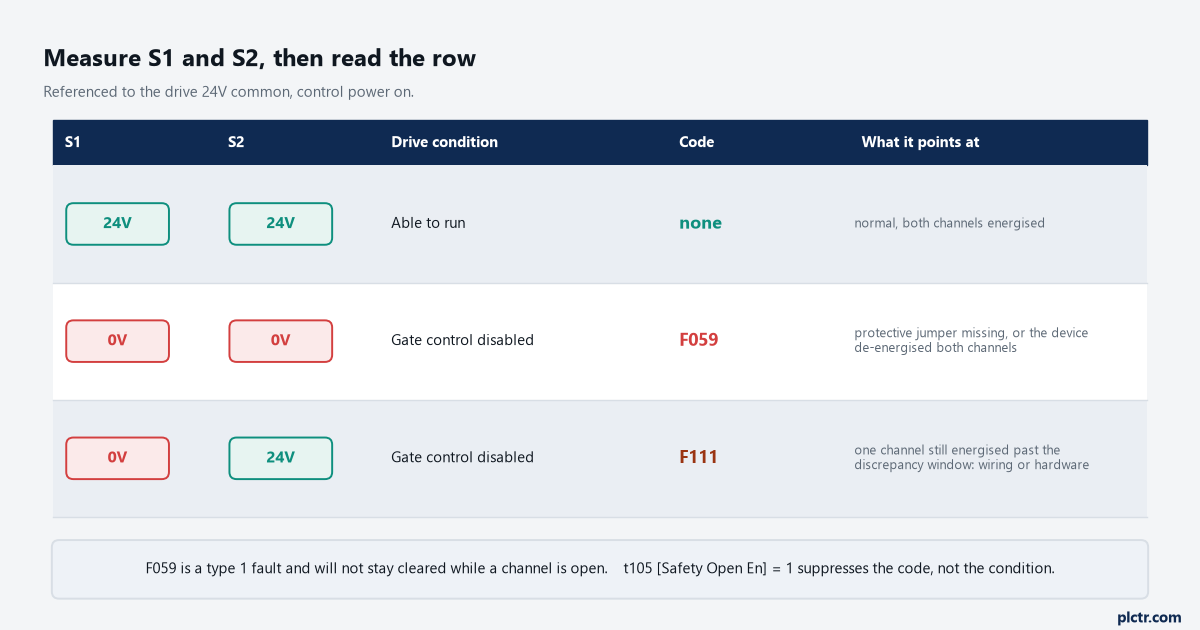
What you measure at the terminals against what the drive will be showing. The bottom two rows are the pair that gets blamed on the drive.
What an open channel does not do for you
Safe torque off removes torque. It does not remove voltage.
The manual says so in as many words: the function “is suitable for performing mechanical work on the drive system or affected area of a machine only. It does not provide electrical safety.” In safe torque off mode hazardous voltages may still be present at the motor. Two more limits are printed alongside that one. By itself the function initiates a coast-to-stop, so an application needing a different stop action needs an additional protective measure the drive does not provide. And if two output IGBTs fail after safe torque off has controlled the outputs off, the drive may still supply energy for up to 180 degrees of rotation in a two-pole motor before torque production ceases.
There is also a detection limit that bears directly on intermittent faults. If an external fault sits on the wiring or circuitry controlling S1 or S2 for a period of time, the safe torque off function may not detect it, and when that external fault clears the function will allow an enable condition again. Faults in the external wiring have to be detected by external logic or excluded by protecting the wiring in ducting or armour, per EN ISO 13849-2. A safety channel run through a flexing cable on a hinged door is the case that clause is written about.
One more wiring condition, easy to miss on a retrofit: where the safety inputs are fed from an external +24V supply rather than from S+, that supply has to be SELV, PELV or a low voltage Class 2 circuit.
Field notes
The spare that arrived stripped. Two 525s sat on a shelf for a conveyor line, both used for a bench demo years earlier, both with the protective jumper robbed for something else. The first went in during a breakdown and threw F059, the second did the same an hour later, and the drives were blamed until somebody laid them next to a boxed one. Receiving checks on that shelf now include the safety terminals.
Half a circuit that passed every functional test. A packaging machine had a gate switch through a safety relay, one output to S1, and a jumper from S+ to S2 because the second output pair was already spoken for. Opening the gate did stop the motor, so it passed every test anyone ran on it. It failed the audit, correctly: with S2 permanently energised, the dual-channel structure the machine had been sold on did not exist. The fix was a relay with another pair of outputs.
Frequently asked questions
Can F059 be suppressed in software?
The annunciation can. t105 [Safety Open En] sets the action when both safety inputs are de-energised: 0 “FaultEnable” is the default and gives you F059, 1 “FaultDisable” does not. What it does not change is the drive’s behaviour, since with both channels open the gate control circuit is disabled either way and no parameter makes the drive produce torque. Setting it to 1 also changes how the network Ready bit behaves, which is worth reading against A574 [RdyBit Mode Cfg] before anyone touches it.
What clears it?
Energise the channels first, because the code reports their present state. After that it clears like any other fault: A551 [Fault Clear] set to 1 “Reset Fault” or 2 “Clear Buffer”, a power cycle, or a digital input configured as 13 “Clear Fault” through t062, t063 or t065 to t068 [DigIn TermBlk xx].
The safety inputs are live and the drive still will not start.
The manual’s symptom table for “motor does not start” lists the safety inputs as one check among several, alongside the wire jumper between I/O terminals 01 and 11, the sink/source jumper setting, and P046, P048 and P050 [Start Source x]. Terminal 01 is always a stop input, and that jumper going missing gives you a drive that will not start with no safety fault at all.
Next step
Get the drive’s fault codes into the controller so the next F059 arrives with a timestamp rather than a phone call, and check the safety channel wiring against the exclusion requirement above while the cover is off. The controller side of drive faults and motor control is covered in PLC motor control and VFD setup, the dual-channel architecture this drive plugs into is in PLC safety interlock systems, and the vocabulary behind Category 3 and PLd is in functional safety in PLC programming. If you are adding the drive to a Logix project rather than fixing one, start with adding a PowerFlex AC drive to a Studio 5000 project.
Primary source throughout: Rockwell Automation, PowerFlex 520-Series Adjustable Frequency AC Drive User Manual, publication 520-UM001O-EN-E, September 2025. Appendix G for the safe torque off function, Chapter 4 for the fault table and symptom checks, Chapter 3 for t105, t106 and A551.