Input assembly instance 1, output instance 2, configuration instance 6 at a size of 0. Those four numbers are what a PowerFlex 525 wants from the ETHERNET-MODULE profile, and they sit in a table on page 56 of Rockwell publication 520COM-UM001B; type the wrong instance number for some other device and Logix Designer comes back with 16#0117, Connection Request Error: Invalid Connection Point. A generic EtherNet/IP module is what you add when the Select Module Type dialog has nothing for the box in front of you and nobody shipped you an EDS file. Five things decide whether the connection opens: two assembly instance numbers for data, one for configuration, a size for each, and the Comm Format that quietly sets the unit those sizes are counted in. The IP address and the RPI come after.
Examples here are Studio 5000 v33 talking to a 1756-EN2T in a 1756-L83E chassis.
When you need a generic EtherNet/IP module rather than a real profile
There are three ways a device gets into the I/O tree.
If the catalogue has the device, use it and stop reading here. The profile knows the instance numbers, builds the tags with real member names, and you never see an Assembly Instance box at all, which is the path in adding a new module in Logix Designer. If the vendor supplies an EDS file, register it first with the EDS hardware installation tool in RSLinx, because on a modern Logix Designer an EDS file can generate a module profile, and a generated profile still beats typing numbers by hand. The generic profile is what is left over: third-party valve manifolds, IO-Link masters, bench scales, vision cameras, older drives, anything whose vendor ships a PDF and a smile.
You are doing the profile’s job by hand, and the controller will believe whatever you type.
Where the instance numbers actually live
In the device’s own manual, under the Assembly Object, class code 04 hex.
Every EtherNet/IP device exposes its I/O as CIP assemblies, and each assembly has an instance number and a length in bytes. The vendor has to publish those or nobody can talk to the device without an EDS file, so they are in there somewhere: an appendix called EtherNet/IP Objects, a chapter called Configuring the I/O, or a table headed Assembly Instances. Rockwell’s own two examples put them in the configuration chapter. The PowerFlex 525 uses instance 1 for input, 2 for output and 6 for configuration, with a configuration size of 0 (520COM-UM001B, page 56). A PowerFlex 755 with a 20-750-ENETR uses exactly the same three numbers (750COM-UM001G, page 94). Plenty of third-party devices use 100 and 101, or 112 and 113, and a device that takes no configuration data at all still wants a legal instance number in the Configuration box with a size of 0.
So 1, 2 and 6 are a Rockwell drive habit rather than an EtherNet/IP standard.
The Size box counts whatever the Comm Format told it to
This is the part that eats an afternoon.
Comm Format on the generic profile is a dropdown: Data – SINT, Data – INT, Data – DINT and a few variations. It does two jobs. It sets the data type of the module-defined tags Logix Designer creates for you, and it sets the unit that the Input Size and Output Size boxes are counted in. Rockwell says so twice, in two manuals, about the same dialog. For the PowerFlex 525 the instruction is “Comm Format: Data – INT” and then “enter the number of 16-bit words that are required for your I/O in the Input Size and Output Size boxes”. For the PowerFlex 755 it is “Data – DINT” and “enter the number of 32 bit words”. Nothing on the dialog tells you which one the vendor’s byte count assumed.
Device manuals do not talk in words. CIP assemblies are byte arrays.
| Comm Format | One unit | A documented 20-byte assembly |
|---|---|---|
| Data – SINT | 1 byte | Size 20 |
| Data – INT | 2 bytes | Size 10 |
| Data – DINT | 4 bytes | Size 5 |
Leave the format on DINT and type 20 because the manual said 20, and the connection request asks the device for 80 bytes. The device refuses. You get 16#0109 and a size field that still looks right in every screenshot you compare it against.
The two Rockwell drives show the same arithmetic from the other side. A PowerFlex 525 on the generic profile needs a minimum Input Size of 4: Logic Status, Feedback, and two 16-bit words the manual describes as memory allocation for the Generic Ethernet module profile. A PowerFlex 755 needs a minimum Input Size of 3, being Logic Status, Feedback and one 32-bit word for the same purpose. Two INT words. One DINT word. Both are the same four bytes of pad at the head of the input image, and the count differs only because the Comm Format differs. Those pad words are real and they move your data: on the 525 the input image reads word 0 pad, word 1 pad, word 2 Logic Status, word 3 Feedback, word 4 onwards Datalinks, while the output image has no pad at all and starts with Logic Command at word 0 and Reference at word 1. Rockwell adds the line that explains every “my status word is in the wrong place” post ever written – padwords only apply when using the generic profile, and are not used with the full-featured Add-On Profile. Swap a generic profile for an AOP and every offset in your logic shifts.
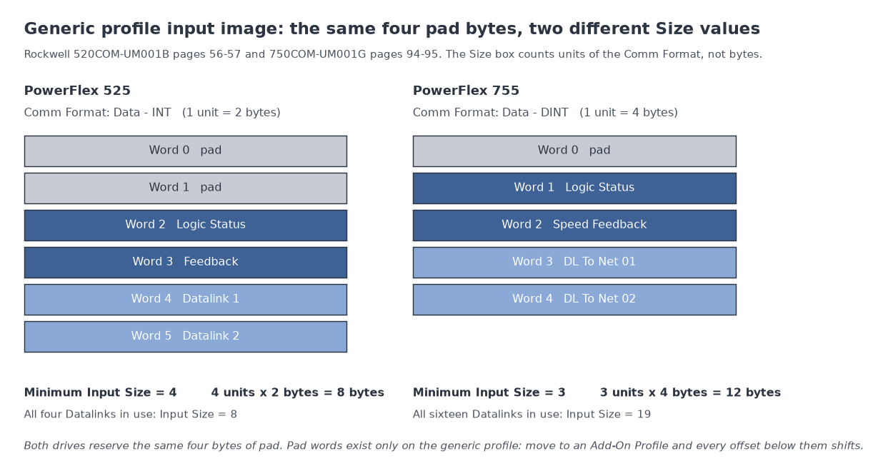
One more thing about Comm Format. You cannot edit it afterwards. Rockwell’s own instruction for changing a Comm Format is to remove the module and recreate it in the I/O configuration tree, which throws away the module-defined tags and every rung that referenced them.
Decide the format before you click Create, not after the panel is wired.
The IP address on that dialog belongs to the device
Not to the card.
The 1756-EN2T already has its own address, set when it went in the rack, and the generic module hangs off it as a child in the I/O tree. The IP Address field on the New Module dialog is the address of the thing at the far end, and both PowerFlex manuals spell that out in the same table: “the IP address of the drive” and “the IP address of the adapter”. Which means the device needs an address before any of this works, and needs to keep it across a power cut, and that is its own job. Assigning an IP address from inside Studio 5000 covers the tool and the BOOTP disable that people forget until the first plant shutdown.
What a fast RPI actually costs on a 1756-EN2T
Rockwell’s guidance for the two drives is 5.0 ms or greater for a PowerFlex 525 and 2.0 ms or greater for a PowerFlex 755, where the field defaults to 20.0 ms. The generic profile will happily accept a number the device cannot honour, and the device answers at connection time with 16#0111, Requested Packet Interval (RPI) out of range. The cost of a fast RPI is packets, and the arithmetic is not subtle. An implicit connection carries two transports, one in each direction, so a single device at a 5 ms RPI is 200 packets per second each way, 400 in total, forever, whether anything changed or not. Twenty devices at 5 ms is 8,000 packets per second through one card.
Then look up what the card can take, and notice what is missing. Table 4 of ENET-UM006C gives the 1756-EN2T 128 TCP connections, 256 CIP connections and 2,000 packets per second for HMI and MSG traffic. In the I/O column, where you wanted a number, it says packet rates for ControlLogix EtherNet/IP communication modules depend on series and firmware revision, and sends you to the EDS file for your exact catalogue number. Firmware revision 3 and later carries more than revision 2 and earlier. Reserve 10% of the bandwidth for explicit messaging on top of all of it.
There is no single packet-rate figure to quote, and anyone quoting one has not read the table.
Here is the part that should change how you pick the number. An implicit connection does not time out at the RPI. It times out at a controller multiplier times the RPI, and the controller firmware picks that multiplier so the timeout lands at or above 100 ms, with a minimum multiplier of 4. Rockwell’s own two examples: a 2 ms RPI gets a multiplier of 64 and times out at 128 ms, a 10 ms RPI gets 16 and times out at 160 ms. So going from 10 ms to 2 ms multiplies your packet load by five and buys 32 milliseconds of earlier fault detection, which on a machine with a 25 ms task is nothing at all. Unless your logic reads the data faster than the RPI, there is nothing else to win.
Set the RPI faster than the task that consumes the data and no faster than that.
The check that proves nothing
The first move everybody makes is to ping the device, and it answers.
RSLinx browses it too, the web page loads, the vendor’s config tool connects, and the I/O connection still will not come up. That is no contradiction. Browsing, MSG traffic and web pages are explicit messaging over TCP, while the I/O connection is implicit messaging over UDP, opened by a request that carries the instance numbers, the sizes and the RPI. A device answers the first and refuses the second all day long. What does tell you something is the card itself: on a 1756-EN2T the NET indicator flashing green means the module has an IP address and has established no CIP connections, or had some and they timed out, and the instruction in ENET-AT003B at that point is to go to the connection originator for the error code. On a panel where the generic device is the only thing configured, that flashing green is the whole diagnosis.
The codes, and what each one is telling you
Open the module’s Properties and read the bottom of the Connection tab.
| Code | String in Logix Designer | What it means on a generic module |
|---|---|---|
| 16#0117 | Connection Request Error: Invalid Connection Point | “The connection is to an invalid port or port that is already in use.” On this profile the connection point is the assembly instance, so check the Input and Output instance numbers first |
| 16#0109 | Connection Request Error: Invalid connection size | “The connection size is inconsistent with that expected.” Size box against Comm Format unit, or a pad word you did not count |
| 16#0118 | Module Configuration Rejected: Format error | Among the listed causes, “the connection instance is not recognized by the module” – that is the Configuration instance number |
| 16#0013 | Module Configuration Rejected: Data size too small | The configuration size you entered is short of what the device wants |
| 16#0015 | Module Configuration Rejected: Data size too large | The same mistake in the other direction |
| 16#0111 | Requested Packet Interval (RPI) out of range | Invalid for this module or for something in the path. Rockwell’s advice is to read the valid range off the Connection tab |
| 16#0100 | Connection Request Error: Module in Use | Something already owns that assembly. An HMI, a second controller, a config tool left connected |
| 16#0113 | Connection Request Error: Module connection limit exceeded | The device’s own connection count, not the card’s |
| 16#0204 | Connection Request Error: Connection request timed out | Nothing answered. Wrong IP, wrong subnet, device off |
| 16#0203 | Connection timed out | It answered, then stopped. The controller keeps removing and remaking the connection |
Those strings are quoted from chapter 4 of 1756-RM018A, and two of them carry a detail worth knowing. For 16#0109 the manual notes that the Additional Error Information field appears as the tag name tied to the connection instance that faulted, which is how you tell which of two connections on the same device broke. And 16#0204 against 16#0203 is the difference between never having had a connection and having lost one, which is the difference between a typing mistake and a cable. The full table used to live in the fault manual and does not any more: 1756-PM014O now points you at a Logix 5000 Controller Fault Codes spreadsheet in the Knowledgebase behind a Rockwell account, while 1756-RM018A still prints it.
Keep that chapter open on the second monitor.
Next
Write the instance numbers, the sizes and the Comm Format into the drawing before you leave site, because none of it is recoverable from the controller once the tags are named Local_Device:I.Data[0]. Set the RPI from the task period rather than from optimism. If a code turns up that is not in the table above, start from Allen-Bradley I/O faults and their causes or the network-side view in EtherNet/IP setup, RPI and faults. And if the device you just wired in by hand turns out to have a real profile after all, throw this away and use the PowerFlex profile route instead.
Publications used: ENET-UM006C-EN-P, 1756-RM018A-EN-P, 520COM-UM001B-EN-E, 750COM-UM001G-EN-P, ENET-AT003B-EN-P, 1756-PM014O-EN-P.