Understanding PLC Programming for Electric Systems
Explore the essentials of PLC in electric systems, including hardware, ladder logic, programming, simulation, testing, troubleshooting, and advanced techniques.Welcome to the intricate world of PLC programming for electric systems! If you’re seeking to grasp the essentials of this pivotal technology that forms the backbone of modern industrial automation, you’ve arrived at the right destination. In the upcoming sections, we will embark on an educational journey starting with the basics of PLC in electric systems, delving into the key components that make up PLC hardware, and unraveling the fundamental concepts behind Ladder Logic. By guiding you through the transition from traditional wiring to the sophistication of PLC programming, we aim to empower you with the skills to create and simulate your very own PLC programs. Furthermore, we’ll explore the critical processes of testing for reliability, troubleshooting common issues, and employing PLCs to optimize electric systems—all the way up to mastering advanced programming techniques. Get ready to unlock the full potential of PLCs and revolutionize your approach to electric system management!
Basics of PLC in Electric Systems
The Basics of PLC in Electric Systems can be regarded as a fundamental cornerstone for individuals looking to grasp the operational essence of modern industrial automation. Incorporating a PLC, or a Programmable Logic Controller, into electrical systems brings about a transformation that enables flexible control over machinery and processes. With its robust design tailored for harsh industrial environments, a PLC provides a reliable solution to complex automation challenges.
Understanding the role of a PLC begins with recognizing its place as a critical component in supervising production lines, managing machinery, and ensuring the seamless execution of repetitive tasks. The PLC’s ability to be programmed and reprogrammed for a myriad of tasks is a testament to its versatility, allowing the integration of several electrical functions into a single unit, thereby enhancing the system’s overall efficiency and operability.
In an electric system, the core of a PLC’s functionality lies in its usage of inputs and outputs to interact with other devices, matching the inputs from sensors and switches to the desired outputs, such as the activation of motors or other machinery. This dynamic interaction highlights the invaluable nature of PLCs in automating processes where precision, timing, and dependability are critical parameters.
To fully appreciate the Basics of PLC in Electric Systems, it is essential to acknowledge the integration of software and hardware working in harmony to create robust control systems. This integration not only simplifies the design and maintenance of these systems but also paves the way for future advancements, solidifying PLCs as foundational elements in the realm of electric and automated systems.
Key Components of PLC Hardware
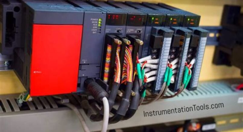
The heart of any Programmable Logic Controller (PLC) is its CPU, or Central Processing Unit, where complex tasks are executed and decisions are made based on logic instructions applied to data received from connected input and output devices. Embedded within a rugged casing that shields against industrial manipulations, the CPU’s functionality hinges on timely processing, often gauged through the lens of scan cycles, with exceptional speed and reliability being paramount to effective automation.
In the realm of PLC Hardware, input and output modules play an invaluable role; these components serve as the primary means for interfacing with machinery and processes, facilitating the flow of digital and analog signals to and from the outside world. Configurability of these modules is essential, as they must adeptly manage a diverse array of sensors and actuators, encompassing everything from straightforward status indications to the nuances of continuous process variables.
Integral to the seamless operation of PLC systems is their power supply unit (PSU), which ensures a stable and reliable source of energy for the PLC to perform its duties. Furthermore, the communication interfaces—spanning from classic serial connections to contemporary Ethernet-based networks—are foundational elements, empowering PLCs to exchange data and collaborate within broader control systems, thereby unlocking the collaborative potential of modern industrial environments.
Beyond the core components, memory within a PLC is a vital repository, archiving programs and maintaining operational data, including variable states and historical information essential for diagnostics and process analysis. When considering the holistic architecture of PLC hardware, one must acknowledge that each component is meticulously crafted to work in concert, ensuring a robust and scalable system that can be tailored to the complex demands of industrial automation and control.
Introduction to Ladder Logic
Ladder logic is the fundamental programming language of programmable logic controllers (PLCs), designed to resemble electrical ladder diagrams, which were used traditionally for wiring relay-controlled systems. Evolved from the need to create a user-friendly way of programming controllers, ladder logic allows the representation of logical relationships between the inputs and outputs of a control system in a format that resembles the rungs of a ladder.
In a typical ladder logic diagram, each rung represents a rule or condition that, when satisfied, can cause an action, such as turning on an output or modifying a value. These rungs are connected by vertical lines that represent the power supply to the circuit. As a programming approach, it is widely praised for its simplicity and ease of understanding; even individuals without a background in programming can interpret and create ladder logic diagrams with some training, making it a staple in industrial automation and control.
Understanding the basics of ladder logic begins with two primary elements: contacts and coils. Contacts serve as the conditional elements – comparable to the input that can either be normally open or closed – which reflect the state of external devices. Coils, on the other hand, act as the outputs which are triggered when the conditions set by the contacts are met. This binary approach manages the control logic for a broad spectrum of applications, from simple machine operations to complex process control.
Moreover, mastering ladder logic involves recognizing common patterns such as sealing circuits, which maintain an output after an initiating input, and timing and counting functions, which enable scheduled controls or event-based operations. With the increasing complexity of systems and the availability of advanced PLC platforms, ladder logic has also evolved to incorporate functions such as data handling and sequential control that extend its applications far beyond basic equipment control.
From Wiring to PLC Programming
The journey from wiring to PLC programming represents a pivotal shift in the world of electric systems, moving from the manual and often cumbersome process of physical electrical wiring to the sophisticated and highly efficient realm of Programmable Logic Controllers (PLC). This evolution not only streamlines the design and functionality of systems but also enhances scalability and adaptability to complex industrial scenarios, where alterations can be implemented via software changes rather than labor-intensive wiring modifications.
Understanding the transition from hardwired logic to programmable solutions is essential for engineers and technicians aiming to stay current in the field. Grasping the concepts behind PLC programming requires a mindset shift, as the tangible connections of relays and timers are replaced by software-based instructions, yet the foundational logic remains constant. This theoretical and practical knowledge is the cornerstone for operators, empowering them to harness the full potential of PLCs in automating and optimizing a plethora of processes within electric systems.
Embarking on the path to master PLC programming necessitates a deep dive into the programming languages that PLCs utilize, with Ladder Logic being the most prevalent due to its resemblance to electrical schematics. Transitioning to this form of programming involves understanding not only the syntax and structure of the language itself but also the intricacies of how digital inputs and outputs within the PLC interface with the connected machinery and equipment, ensuring a harmonious communication between software commands and physical operations.
Lastly, having a firm grasp on migration from traditional wiring to proficient PLC programming is not just about understanding the technical dynamics; it’s about embracing a philosophy of flexibility and efficiency that PLCs introduce. It allows for iterative and swift problem-solving, monitoring, and improvements in electric systems, marking a stage of evolution that is integral to the modern industrial environment, where adaptability is as paramount as the power running through the system itself.
Creating Your First PLC Program
Embarking on the journey to create your first PLC program can be both exciting and challenging; it marks the transition from theoretical understanding of PLC systems to practical application, enabling one to transform intricate electric system requirements into executable logic that PLCs can interpret and act upon. An essential step in this process is the thorough comprehension of the functional specifications of the system you’re aiming to control or monitor, which involves a deep dive into the sensory inputs and actuator outputs alongside their corresponding actions and reactions that the PLC is expected to manage.
For beginners, starting with a simple project that involves a finite number of inputs and outputs is advisable, thus allowing the novice PLC programmer to grasp the core concepts without becoming overwhelmed by complexity; such an approach fosters a clear understanding on how to structure a PLC program, how to utilize programming software to input instructions, and how to visualize the flow of operations within the PLC ladder logic, which is a common graphical programming language used in the industry. A meticulous approach to defining each step and expected outcome in your PLC program lays a robust foundation for more advanced projects in the future.
Once the groundwork is laid, the next step is to construct the ladder logic or another suitable programming language that the chosen PLC understands; here, one must pay vigilant attention to correctly placing contacts and coils in the diagram, which represent the switches and relays in the control system, respectively. Furthermore, testing each rung of the ladder logic is paramount to ensuring that the logic mirrors the intended behavior, such as turning on a motor when certain conditions are met or stopping a conveyor belt when an emergency button is pressed, and it helps to preempt any unforeseen errors that might emerge during the operation of the electric system.
At this stage, it is crucial to iterate and refine the PLC program to polish its functionality; a practice that often involves simulating the program using PLC software or using a test mode on the PLC itself, observing how the program behaves with various inputs, and making adjustments as required. This iterative process not only enhances the reliability of your PLC program but also instills a more profound understanding of the nuances of PLC programming, thus paving the way for tackling more sophisticated programs and optimizing electric systems to their highest efficiency and effectiveness in the future.
Simulating PLC Operations Virtually
Simulating PLC operations virtually is a critical process that enables engineers and programmers to test and validate their programmable logic controller (PLC) designs without the need for physical hardware. This practice has become an indispensable tool in the realm of automation and control systems, providing a cost-effective and efficient method to foresee how a PLC would react in various scenarios. With sophisticated simulation software, it’s possible to mimic the intricate behaviors of a PLC and its interaction with other system components, making it a powerful approach for optimizing system performance prior to implementation.
Utilizing a virtual environment for simulating PLC operations offers exceptional advantages, such as the capacity to evaluate the impact of code changes extensively and ascertain the reliability of the PLC program under diverse operating conditions. These environments can often emulate the electrical characteristics and dynamics of the connected machinery, thereby enabling the early detection of potential issues in system design. There is also the aspect of safety; by conducting these tests virtually, there’s a substantial reduction in risks associated with testing on actual equipment, especially during the early stages of development.
Another facet of virtual PLC simulation is its role in education and training. For learners and new technicians, the ability to interact with a simulated PLC system offers invaluable hands-on experience without the pressure of working with costly equipment. It serves as an interactive platform to understand complex concepts and practice programming skills. Advanced simulation tools can replicate real-world scenarios and problems, helping users to develop proficiency in troubleshooting and enhancing their overall understanding of how PLCs integrate into broader electric systems.
Ultimately, the goal of virtually simulating PLC operations is to streamline the development process of control systems, reduce costs associated with prototyping and testing, and accelerate the transition from concept to deployment. As we look towards a future of increasingly complex and intelligent automation, the role of PLC simulation will undoubtedly grow, becoming an indispensable asset for designers aiming to refine their systems for peak performance and reliability while navigating the complexities of modern industrial applications.
Testing PLC Code for Reliability
In the field of industrial automation, ensuring the reliability of a Programmable Logic Controller (PLC) system is paramount, which is why testing PLC code for reliability is a critical step in the development cycle. A comprehensive testing process not only verifies the correctness of the PLC program against its intended function but also exposes potential issues that could lead to system malfunctions or downtime. By rigorously scrutinizing the PLC code through various simulated and real-world scenarios, engineers can uncover hidden bugs and optimize program performance to withstand the demanding conditions of industrial environments.
Thorough testing involves subjecting the PLC code to a battery of tests, including but not limited to unit testing, integration testing, system testing, and acceptance testing. Each type of test serves a distinct purpose; for example, unit testing focuses on individual function blocks or routines, while integration testing evaluates the interactions between those blocks. System testing examines the complete integrated system functioning in harmony, and acceptance testing ensures that the system meets all the specified requirements and is ready for operation in the real world.
One cannot overstate the importance of simulating real-time conditions when testing PLC code for reliability. Simulators and test rigs act as proxies for the actual machinery and processes controlled by the PLC, thereby allowing testers to introduce various inputs, including edge cases and unexpected scenarios, without risking damage to physical assets. Through this method, testers can observe the PLC program’s reaction to extreme or erratic conditions, assessing its stability and robustness. It also provides a safe environment to validate safety mechanisms and emergency procedures programmed within the PLC.
Finally, a best practice in PLC code testing is the implementation of automated regression tests that can be rerun every time a change is made to the codebase. This ensures that new changes do not introduce regressions or adversely impact existing functionalities. With a strong emphasis on a meticulous and well-documented testing process, engineers are better equipped to deliver PLC systems that perform reliably over the long term, reducing the risk of costly failures and ensuring the seamless operation of critical industrial processes.
Troubleshooting Common PLC Issues
When attempting to resolve common PLC (Programmable Logic Controller) issues, it is vital to have a solid understanding of both the hardware and software components of these sophisticated electronic systems. One prevalent issue that frequently arises involves communication failures, which can stem from improper wiring, issues with the network protocols, or a malfunction in the hardware interfaces that connect the PLC with other devices. Determining the root cause necessitates a systematic approach to diagnose the communication layers, often starting with physical connections and working up to software configurations.
Another issue that practitioners may encounter is related to faulty input/output (I/O) modules. Symptoms of such faults can include erratic behavior of the PLC outputs, unresponsive system states, or unexpected halts in the automation process. To address this, it is imperative to check the LED indicators on the I/O modules for correct status signals, scrutinize the wiring for any signs of damage or loose connections, and utilize diagnostic tools to ensure each module is functioning as intended within the PLC’s programmed logic.
Power supply problems can also lead to perplexing difficulties with a PLC‘s operation. Uneven or interrupted power supply can cause the PLC to reset unexpectedly or operate in an unstable fashion. It is fundamental to examine the power supply unit, verify that all voltage levels are within specified limits, and inspect for any signs of wear or environmental factors that could be influencing the power quality. On some occasions, replacing or repairing the power supply unit is the most straightforward solution to these types of PLC issues.
Lastly, software-related glitches within the PLC programming can provoke a multitude of issues, ranging from simple logic errors to complex timing conflicts within the control process. Troubleshooting these requires an in-depth analysis of the ladder logic or other control algorithms used in the programming of the PLC. Debugging tools provided by the PLC programming software can be invaluable, helping to trace and correct any erroneous code, fine-tune timing sequences, and ensure that the program accurately reflects the intended operational procedures for the electric system it governs.
Optimizing Electric Systems with PLC
When it comes to enhancing the efficiency, reliability, and overall performance of electric systems, the value of Programmable Logic Controllers (PLCs) cannot be overstated. Utilizing sophisticated PLC strategies is critical in meeting the complex demands of modern electrical networks. By integrating robust programming with real-time monitoring, PLCs are key in intelligently managing power distribution and effectively controlling various components within the system. The optimization process takes into consideration an array of variables, such as load requirements, energy consumption patterns, and the system’s capacity for scalability.
Advances in PLC technology have paved the way for unprecedented levels of system integration and automation. By employing advanced algorithms and data analytics, PLCs can predict potential system bottlenecks and accordingly adjust power flows to mitigate risks and reduce inefficiencies. This ability to preemptively manage resources contributes significantly to the longevity and dependability of electric systems. Furthermore, managing operational parameters to prevent overload and strategically sequencing equipment startup are just a few examples of how PLCs can extend equipment life and optimize maintenance schedules.
Synchronizing and coordinating multiple system components, PLCs stand at the forefront of facilitating adaptive control strategies pertaining to energy use. With the advent of the Industrial Internet of Things (IIoT), PLCs can now communicate with a myriad of smart devices, providing operators with a comprehensive overview of the electric system’s health. Data-driven decisions enabled by PLCs are essential in reducing wastage and promoting sustainable energy practices, effectively heralding a new era in electric system management where each kilowatt-hour is judiciously utilized.
Finally, modern PLCs are equipped with remote monitoring capabilities, allowing maintenance teams to diagnose and resolve issues promptly, often before they escalate into critical failures. This proactive approach enabled by PLC diagnostics can vastly improve uptime and ensure that electric systems operate within optimal parameters. Implementing such smart strategies and PLC programming techniques is a testament to the immense potential of PLCs in revolutionizing the way we optimize and manage electric systems in an increasingly demanding and dynamic energy landscape.
Advanced PLC Programming Techniques
Delving deeper into the realm of Programmable Logic Controllers (PLC), one can uncover a multitude of sophisticated programming paradigms that are designed to enhance both the efficiency and functionality of electric systems. One of the most intricate yet profoundly efficient advanced PLC programming techniques is the implementation of structured text programming, which is akin to the languages used in computer programming, allowing for an expansive range of commands and logical operations that can be elegantly tailored to fulfill complex automation tasks.
Moreover, seasoned PLC programmers often invoke the power of Function Block Diagrams (FBD) to visually represent and reuse common processes; this technique not only streamlines the process of program development but also fosters better understandability and maintenance of the code among multiple users or teams. With these intricate diagrams, the interconnections of various elements within an electric system are meticulously illustrated, facilitating an overarching view of system operation, and permitting targeted optimizations that can substantially boost system performance.
In addition, as one delves into advanced PLC programming techniques, the utility of advanced instructions such as PID control loops can be of paramount importance, particularly in applications requiring precise control of variables like temperature, pressure, or flow rate. These loops allow for real-time adjustments and refinements ensuring that the system responds accurately to dynamic conditions, thus mitigating oscillations and promoting the desired stability within the automated processes of an electric system.
Lastly, the implementation of networking and remote communications within PLC programming signifies a leap towards modernization and interconnectivity of industrial control systems. It unlocks the doors to centralized monitoring, control, and data acquisition across various PLCs within a network. This advanced technique not only simplifies the management of large-scale industrial operations but also enables predictive maintenance through real-time data analytics, setting the stage for Industry 4.0 and beyond.
Frequently Asked Questions
What is a PLC and what role does it play in electric systems?
A PLC, or Programmable Logic Controller, is an industrial digital computer which has been ruggedized and adapted for the control of manufacturing processes, such as assembly lines, or robotic devices, or any activity that requires high reliability control and ease of programming and process fault diagnosis. In electric systems, PLCs are crucial for automating electrical processes, ensuring consistent and precise control of equipment and machinery.
Can anyone learn PLC programming, or is it necessary to have a background in electrical engineering?
While a background in electrical engineering can be beneficial for understanding the fundamentals of electric systems and complex programming tasks, anyone with an interest and dedication can learn PLC programming. There are many resources and courses available that start with the basics and gradually increase in complexity.
What are the common programming languages used in PLC programming?
The most common programming languages used in PLC programming include Ladder Logic, Function Block Diagram (FBD), Structured Text (ST), Instruction List (IL), and Sequential Function Chart (SFC). Each language has its own strengths, and the choice of language often depends on the specific application and the preference or expertise of the programmer.
How do PLCs differ from traditional computers in terms of hardware?
PLCs are designed for industrial environments, which means they are built to withstand extreme temperatures, vibration, and electrical noise. Their hardware includes special input/output interfaces for sensors and actuators, and they often have features such as real-time clocks and battery-backed memory. Unlike traditional computers that typically have a general-purpose design, PLCs are specifically tailored for real-time control tasks.
What is the importance of simulation in PLC programming?
Simulation is critically important in PLC programming because it allows programmers to test and debug their control logic before implementing it in the actual machinery. This can save time and resources by catching issues early and can prevent potential damage to the equipment or downtime caused by programming errors.
Could you explain how a PLC can improve safety in electric systems?
PLCs contribute to safety in electric systems by providing reliable and precise control of machinery and processes. They can be programmed with interlocks, emergency stops, and alarm systems to prevent accidents. PLCs can also monitor system performance and detect irregularities that may indicate potential hazards, allowing for proactive maintenance and intervention.
What are some future trends in PLC programming that electric system professionals should be aware of?
Some future trends in PLC programming include the integration of IoT (Internet of Things) functionalities, advanced analytics, cloud computing, and machine learning. These advancements will allow for greater connectivity, remote monitoring, predictive maintenance, and smarter decision-making in electric systems. Professionals should stay informed on these trends to enhance system efficiency and to keep their skills relevant in an evolving industry.