Three tags come back from the edge box and the whole design sits in them: ML.Score, ML.Valid and ML.Seq, a heartbeat counter that has to keep moving or a stale timer in the CompactLogix throws the score away after ten seconds. Under it is a 15 kW transfer pump on a 5069-L320ER, with the model itself on a fanless Linux box beside the panel. The useful question on a machine learning plc project is not which algorithm. It is what the PLC has to publish, how the answer gets back, and what happens when the box goes quiet. This is the layout I use, with a pump anomaly detector on a CompactLogix line as the example.
Put the model where it belongs
A Logix or S7 CPU can run a small linear model or a decision tree if you type the coefficients into Structured Text, and sometimes that is right. Anything that needs a Python runtime, a GPU or a retrain every few weeks does not go in the controller. Two places it does go:
| Where | What it is | Reads tags via | Writes back |
|---|---|---|---|
| Edge PC or gateway | Fanless Linux box beside the panel, containers, Python with scikit-learn or an ONNX runtime | EtherNet/IP through pycomm3, a Kepware or Ignition driver, or OPC UA where the controller firmware offers a server | A few REAL, DINT and BOOL tags over the same link |
| Vendor in-rack module | Siemens TM NPU in an S7-1500 rack runs a trained neural network and hands the result to the CPU; Rockwell FactoryTalk Analytics LogixAI sits in a ControlLogix chassis, learns from controller tags and writes a prediction or anomaly score back to a tag | Backplane | Backplane, same tag discipline as the edge box |
The in-rack modules save a network hop and the IT conversation about a Linux box on the machine VLAN. They do not change the contract: training happens off the CPU, in a tool or in the module itself, the model needs the same clean tags, and the CPU owns every output. Check either module’s lifecycle status before you design around it.
Pick problems the model can actually solve
| Problem | Verdict | Why |
|---|---|---|
| Anomaly on motor current or vibration | Yes | A healthy baseline exists and the score only has to say “this is not normal” |
| Cycle-time drift on a machine | Yes | Per-cycle time from the PLC plus a trend is often enough; the model picks the change earlier |
| Predictive alarm with lead time | Yes, as advice | A failing bearing, a leaking seal, a blinding filter: all of them show in current and pressure days before the trip |
| Sequencing and interlocks | No | Deterministic logic that was tested and signed off; a model has no business here |
| Safety functions | Never | Nothing in IEC 61508 or ISO 13849 certifies a model; keep the tag out of the safety task |
Even the yes rows come back as an advisory; the controller decides what to do with it under logic you can read.
Give the model clean tags before you give it data
A model trained on a raw current signal with starts, stops and cleaning cycles mixed in learns that starting is an anomaly. Most of the data hygiene lives in the PLC program, not in Python.
- Publish the machine state as one INT from the sequence, the same state model the OEE logic uses. The model is trained on state 2, running, and nothing else.
- Increment a cycle counter every scan of the periodic task the tags are produced in. It is the join key between PLC data, edge data and the alarm log.
- Compute the fast statistics in the PLC. A 100 ms task can hold min, max and mean of the current over each second; the edge reads those once a second and misses nothing.
- Publish quality. Module fault bits from a GSV on the I/O module, the drive connection status, and a range check on every analog signal, packed into one DINT.
- Stamp the wall clock with a GSV WallClockTime rung, and set that clock from the same NTP source as the edge box. Use the counter for joins and the clock for humans.
Over OPC UA every value carries a StatusCode and a SourceTimestamp; a value with a bad status is not a sample. The server side is covered in OPC UA PLC integration.
Worked example: a pump anomaly detector on a CompactLogix line
The machine is a 15 kW centrifugal transfer pump on a PowerFlex 525, controlled by a 5069-L320ER in Studio 5000 v33. The edge box is a fanless industrial PC running Debian, Python 3.11, pycomm3 and scikit-learn. Every number below is from this line.
| Tag | Type | Produced by | Notes |
|---|---|---|---|
Pump.State | INT | Sequence routine | 0 stopped, 1 starting, 2 running, 3 stopping |
Pump.Cycle | DINT | 100 ms periodic task | Increments every scan, rolls over, join key |
Pump.I_Mean Pump.I_Max | REAL | 100 ms task, held per second | Drive output current datalink, amps |
Pump.Speed_Hz | REAL | Drive input assembly | Output frequency |
Pump.P_Disch | REAL | 5069-IF8 | Discharge pressure, bar |
Pump.Q_Flow | REAL | 5069-IF8 | Flow, cubic metres per hour |
Pump.Quality | DINT | Quality routine | Bit 0 drive comms, bit 1 analog card, bit 2 flow in range, bit 3 pressure in range |
ML.Score | REAL | Edge box | 0.0 normal to 1.0 abnormal |
ML.Seq | DINT | Edge box | Plus one on every write, the heartbeat |
ML.Valid | BOOL | Edge box | Model loaded and inputs were good |
The edge loop reads the pump tags once a second, keeps the sample only when Pump.State is 2 and all four quality bits are set, scores it with an Isolation Forest trained on three weeks of running data, and writes three tags back.
import time
from pycomm3 import LogixDriver

TAGS = ['Pump.State', 'Pump.Cycle', 'Pump.I_Mean', 'Pump.I_Max',
        'Pump.Speed_Hz', 'Pump.P_Disch', 'Pump.Q_Flow', 'Pump.Quality']

with LogixDriver('192.168.10.20') as plc:
    seq = 0
    while True:
        vals = {r.tag: r.value for r in plc.read(*TAGS) if not r.error}
        ok = vals.get('Pump.State') == 2 and vals.get('Pump.Quality') == 0b1111
        score = model_score(vals) if ok else 0.0      # 0.0 .. 1.0, model in a separate module
        seq += 1
        plc.write(('ML.Score', score), ('ML.Seq', seq), ('ML.Valid', ok))
        time.sleep(1.0)
The PLC side is a watchdog and a permissive. ML.Seq must keep changing; if it stops for 10 s, ten missed writes on this line, the score is stale and the advisory drops.
(* ML_Watchdog routine, 100 ms periodic task, 5069-L320ER, Studio 5000 v33 *)

IF ML.Seq <> ML_Seq_Last THEN
    ML_Seq_Last := ML.Seq;
    Stale_Tmr.Reset := 1;                 (* fresh write, restart the stale timer *)
ELSE
    Stale_Tmr.Reset := 0;
END_IF;
Stale_Tmr.PRE := 10000;                   (* 10 s, ten missed one-second writes *)
Stale_Tmr.TimerEnable := 1;
TONR(Stale_Tmr);
ML_Stale := Stale_Tmr.DN;

(* clamp the score, no LIMIT in Logix ST *)
IF ML.Score > 1.0 THEN
    ML_Score_Clamped := 1.0;
ELSIF ML.Score < 0.0 THEN
    ML_Score_Clamped := 0.0;
ELSE
    ML_Score_Clamped := ML.Score;
END_IF;
Score_Hi := ML_Score_Clamped >= 0.8;      (* threshold set from the worst week of training data *)

(* the same permissive as rung 4 in the ladder image; keep it in one place, not both *)
ML_Advisory := ML.Valid AND NOT ML_Stale AND Score_Hi;

(* 15 s of continuous advisory before anyone is told *)
Adv_Tmr.PRE := 15000;
Adv_Tmr.TimerEnable := ML_Advisory;
TONR(Adv_Tmr);
Advisory_Alarm := Adv_Tmr.DN;
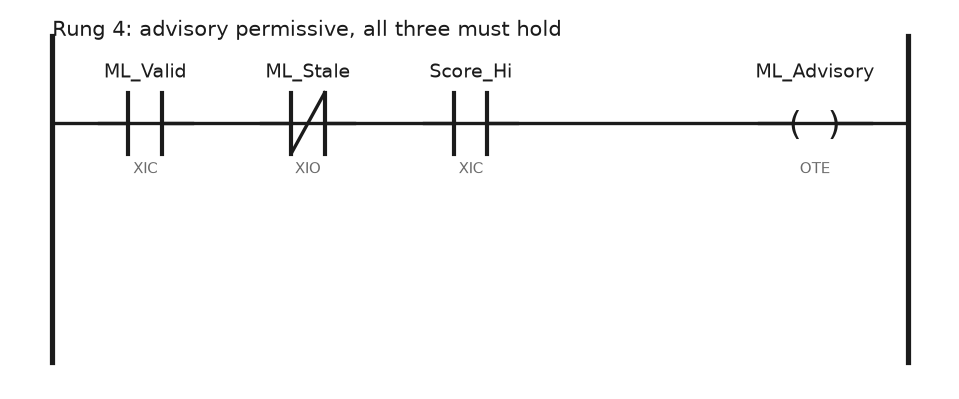
Rung 4 is the whole permissive, and the maintenance team can read it at two in the morning.
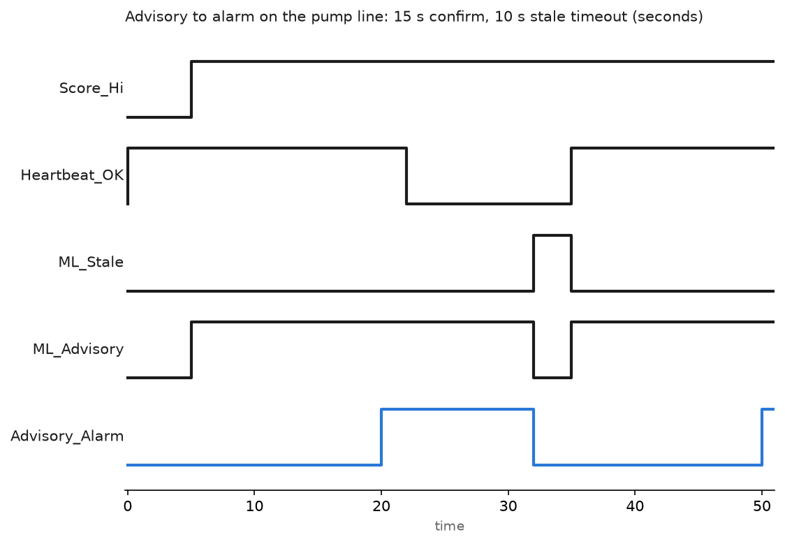
Read the chart against the code; Heartbeat_OK on the chart is ML.Seq still changing. The score crosses 0.8 at 5 s and the advisory comes on at once. The 15 s confirm timer raises Advisory_Alarm at 20 s. At 22 s the edge box stops writing, the container was restarting, and at 32 s the 10 s stale timer expires, so the advisory and the alarm both drop. The heartbeat is back at 35 s and the advisory returns because the score is still high. TONR is non-retentive and was released at 32 s, so the alarm needs the full 15 s again and re-arms at 50 s. The operator saw an alarm, then a clear, then a second alarm. Both alarms were true.
Feed the answer back as advice, not as a command
Advisory_Alarm goes to the alarm server as a low-priority alarm with its own reason code. On this pump it reads “pump current pattern abnormal, check strainer and seal” and nothing trips. Alarm handling is the usual one from PLC analog alarm ALMA.
When a model is allowed to move something, it moves a trim inside a band the PLC owns. A dryer setpoint trim of plus or minus 3 degC around the recipe value, clamped with an IF, applied only while the same validity and stale checks hold, and reverting to zero trim the moment they do not. The operator has a button to switch trim off and the switch is logged.
Field notes
Clocks four minutes apart. The edge box was on NTP, the controller clock had been set by hand at commissioning and drifted 4 min. Historian rows and alarm log rows never lined up. The cycle counter fixed the join, and a rung that writes the clock from the SCADA once a day fixed the humans.
Current sampled too slowly. The edge read Pump.I_Mean from the drive at 1 s and never saw the current swings from cavitation, so the model called cavitation normal. Moving those three statistics into the 100 ms task and publishing Pump.I_Max per second gave the model the swings without adding network load. Rates and deadbands are in PLC data logging best practices.
Thirty alarms, zero labels. The detector raised 30 advisories in three months and nobody wrote down what the fitter found. Without labels there is no way to say whether 0.8 is the right threshold or whether the model is watching the strainer or the seal. The fix was a reason-code popup on the advisory alarm: five choices and a free text field.
Setpoint stuck after a reboot. On an earlier project the edge box wrote a trim straight into a setpoint tag with no validity bit. It rebooted for an update and the last value sat in the controller for six hours. That is the reason for ML.Seq and the stale timer.
Frequently asked questions
Can a PLC run a neural network itself?
A small one, yes: multiply and add in ST with the weights in an array. Anything larger goes on an in-rack module or an edge PC, and training always happens off the controller.
What sampling rate does the model need?
Faster than the effect you are hunting. A bearing defect shows in vibration at hundreds of hertz and up, a job for an accelerometer with its own analyser feeding a scalar into the PLC. Cavitation shows as current swings a few hundred milliseconds long, which a 100 ms task catches as a per-second max. Seal wear shows over days; one value a minute is plenty.
Do I need a data scientist?
For an anomaly detector on one pump, no. A controls engineer who can read a pandas dataframe and knows what “running” means on that machine will beat a data scientist who does not. For a plant-wide soft sensor, get the help and keep the tag contract above.
Next step
Build the state model and the quality DINT first; without them nothing downstream is worth training. The signals that feed this kind of detector, and what vibration and current actually tell you, are in PLC predictive maintenance. Then measure the task load you added, as in PLC scan time and cycle time, before the edge box goes live.