On a ControlLogix 5580, Tank_Level_Alarm.Status.3 is set. Every one of HHInAlarm, HInAlarm, LInAlarm and LLInAlarm reads 0, the transmitter has been sitting at 94.0 against a high-high limit of 90.0 for six minutes, and no alarm exists anywhere on the system. Nothing is faulted and the ALMA instruction is scanning.
Status bit 3 is AlarmLimitsInv, and somebody typed a low limit above a low-low limit from a faceplate.
That is the shape of controller-based alarming, both halves of it. The good half: the detection, the timestamp and the acknowledge state all live in the controller, so an alarm raised during a network drop is still there with its original time when the HMI comes back, and the same alarm looks identical to every client. The bad half: an ALMA with an invalid limit set does not fault and does not annunciate — 1756-RM018A says that when AlarmLimitsInv is set, the instruction clears all level conditions active bits, and until the fault is cleared no new level conditions can be detected.
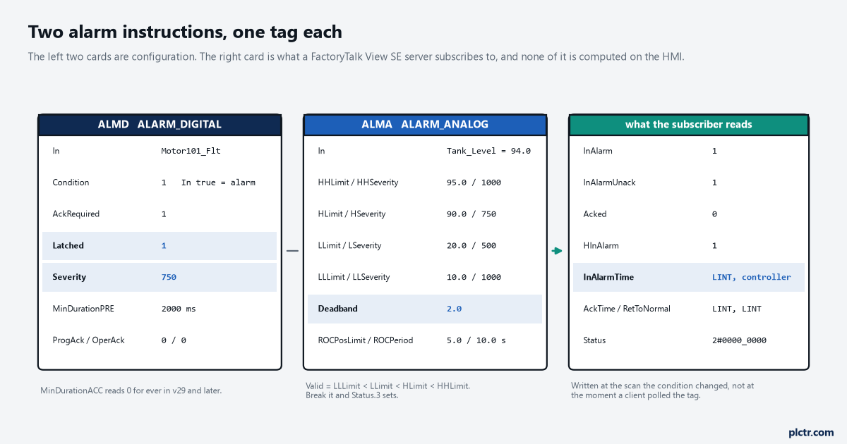
Two instructions, one idea. What you configure is on the left; what the subscriber reads is on the right, and the timestamps in the middle are the reason to do this in the controller at all.
What actually moves, and what stays on the HMI
The instruction detects. It does not display, and it does not log.
An ALMD or an ALMA evaluates its condition, stamps the transition, holds the acknowledge state and publishes all of that on its own tag. The screen, the banner, the historian and the audit trail are still somebody else’s job — 1756-RM018A puts it in one line, that the Logix-based alarm instructions integrate alarming between the RSView SE applications and Logix 5000 controllers, which today means a FactoryTalk View SE server subscribing to the controller rather than polling a pile of bools and deciding for itself what an alarm is. That division is the whole argument. A tag-based alarm on the HMI is detected when the HMI got round to reading the tag, so its timestamp is a polling artefact and two clients can disagree about the order of two alarms 80 ms apart. An InAlarmTime on an ALMD is a LINT written by the controller at the scan the condition changed.
The cost is real, it is measurable, and it is not the alarm limit.
An ALARM_DIGITAL or ALARM_ANALOG tag is a large structure — dozens of members each, several of them LINT timestamps — and every instance is scanned every pass of whichever task it sits in. The numbers are published: LOGIX-RM002B lists an ALMD on a 5580 or 5380 at 0.574 µs when the alarm state does not change and 1.346 µs when it does, and an ALMA at 0.386 µs with .In false, 1.299 µs with .In true and no change of state, 1.869 µs when one condition triggers and 2.194 µs when two do. Four hundred quiet ALMDs is therefore about 230 µs of scan, which is nothing in a continuous task and a quarter of a 1 ms period. The older families’ figures are in the spreadsheets attached to the 1756-RM087 PDF, which is worth knowing because opening that document in a browser hides the attachments and makes it look empty.
Four hundred alarms all changing state in the same scan is 538 µs, and that is the number to size for.
ALMD, and the two checkboxes that define its personality
ALMD(Motor101Fault, Motor101FaultConditions, Motor101Ack, 0, 0, 0); is the whole call in structured text.
Underneath it are three configuration bools that between them produce four completely different alarms from the same instruction, and the manual prints a timing diagram for each of the four. Condition
In is true; cleared to false, the alarm activates when In is cleared to false, which is how you alarm on a permissive dropping out rather than a fault appearing. AckRequired defaults to true, and clearing it means Acked is simply always true — the alarm still appears and still clears, nobody ever has to touch it. Latched defaults to false, and setting it means the alarm stays InAlarm after the condition goes away until a Reset command arrives. The sentence under Latched is the one worth copying into your standards document: a latched alarm can only be reset when the alarm condition is false. So a reset pressed while the fault is still present does nothing at all, which is correct and is also the single most common “the reset button is broken” call.| Condition | AckRequired | Latched | What you get |
|---|---|---|---|
| true | true | false | ordinary fault alarm, clears itself, needs an ack |
| true | true | true | fault that stays up until someone resets it |
| false | true | false | alarm on loss of a permissive |
| true | false | false | an event in the log, nothing to acknowledge |
MinDurationPRE is the debounce, in milliseconds.
It specifies how long the alarm condition must be met before it is reported, which is the difference between a pressure switch that chatters twice a shift and a pressure switch that raises forty alarms a shift. Its companion MinDurationACC is a trap of the harmless kind: 1756-RM018A states that the value is not used in versions 29 and later of the Logix Designer application and is always 0. Put it on a faceplate as a countdown and it will read zero forever.
The rung condition is not an on/off switch
This is the one that catches people who have written a thousand rungs, because every other instruction in the catalogue behaves the other way.
Read the ladder execution table for ALMD carefully. Rung-condition-in false does not skip the instruction: the manual’s action is that the In parameter is cleared to false and the instruction executes. Combine that with the In operand’s own description — in ladder, In follows the rung condition, set to true if the rung condition is true and cleared to false if the rung condition is false — and the consequence is unavoidable. Conditioning an ALMD rung with a “this alarm is not relevant in Manual” contact does not disable the alarm. It tells the alarm that the condition has gone away, which acknowledges nothing, clears InAlarm, and reports a return-to-normal that never happened. The EnableIn member is explicit that in ladder it corresponds to the rung state and does not affect processing.
Three languages, three answers.
In function block, EnableIn cleared to false genuinely does stop the instruction: it does not execute and outputs are not updated. In structured text, EnableIn has no effect at all and the instruction always executes. In ladder, the rung is the input signal rather than an enable. If you want an ALMD that can be switched off, the mechanism is ProgDisable and ProgEnable — parameters on the instruction, written by your logic — not a contact in front of it.
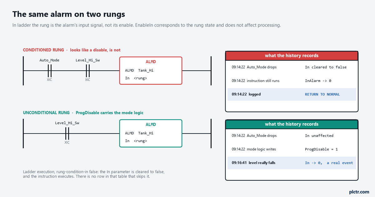
Both rungs are “correct” ladder. The upper one reports the alarm cleared at 09:14:22 because the mode selector moved, and the record it leaves behind says the tank stopped overflowing.
The other half of this is prescan, and it deserves a line of its own.
On prescan the instruction clears InAlarm, clears Shelved, sets Acked true, acknowledges all alarm conditions, clears all operator requests and clears all timestamps. A trip to Program mode and back therefore hands you a project in which every controller-based alarm has been acknowledged by nobody, and every timestamp is gone. That is the documented behaviour and not a bug, but it does mean the alarm history has to live in the subscriber rather than in the tag, and it is a reason to be careful about which alarms you let a download quietly clear.
ALMA: four levels, two rates, and the bit that turns it off
One analog input, six conditions, each with its own acknowledge and its own severity.
The four level conditions are High High, High, Low and Low Low, and the manual states the ordering rules as validity conditions rather than as advice: HLimit < HHLimit < maximum positive float, LLimit < HLimit < HHLimit, and LLLimit < LLimit. Break any of them and AlarmLimitsInv sets, every level condition active bit is cleared, and no new level condition can be detected until it is fixed. That is the failure in the opening paragraph and it is worth understanding why it is a design decision rather than an oversight: an instruction that cannot tell which way round its limits are cannot safely report anything. It is also why a faceplate that lets an operator type any of the four numbers needs range checking on the HMI side, or a ProgDisable-style interlock, because the instruction itself will accept the write and then go quiet.
The other two conditions are rate of change, and they need one number nobody sets thoughtfully.
ROCPeriod is the sampling interval, and the arithmetic printed in the reference is ROC = (current sample of In - previous sample of In) / ROCPeriod, updated when the instruction is scanned following each elapsed ROCPeriod. Set ROCPeriod shorter than the noise on the signal and the rate alarm fires on the noise; set it longer than the event you are trying to catch and it never fires at all. A tank level from a 4-20 mA transmitter scaled in the controller with a couple of percent of ripple on it needs a ROCPeriod long enough to average that ripple out, and the sanity check is to work out what the ripple alone looks like in engineering units per period before choosing the limit. The invalid-configuration bits here are gentler than the level ones: ROCPosLimitInv at Status.5 makes the instruction use ROCPosLimit = 0.0, which the manual says makes positive rate-of-change detection unavailable. Unavailable, quietly, again.
The three numbers that decide whether anyone reads the alarm list
Severity, deadband and minimum duration, and only one of them changes what the controller does.
Severity runs 1 to 1000, where 1000 is most severe and 1 is least, and its description is blunt about what it is for: it does not affect processing of alarms by the controller, but can be used for sorting and filtering functions at the alarm subscriber. The default on an ALMD is 500, which means a project where nobody thought about it has every alarm at the same priority and a banner that is useless the first time three things go wrong together. Out-of-range values are clamped rather than rejected — below 1 the instruction uses 1, above 1000 it uses 1000, and SeverityInv at Status.2 tells you it happened. Deadband is the one that stops chattering, and its description contains the detail that makes it usable: a non-zero deadband can reduce alarm condition chattering if the In value is continually changing but remaining near the level condition threshold, and the deadband value does not affect the transition to the InAlarm state. It only affects the return to normal. So a high alarm at 90% with a deadband of 2 still trips the instant the signal reaches 90 and clears at 88, which is exactly the asymmetry you want and exactly the opposite of what people expect a deadband to do. Its own validity rule is 0 <= Deadband < Span from the first enabled low alarm to the first enabled high alarm, and DeadbandInv at Status.4 means the instruction fell back to 0.0.
Deadband tightens the trip point on nobody. It only widens the clear point.
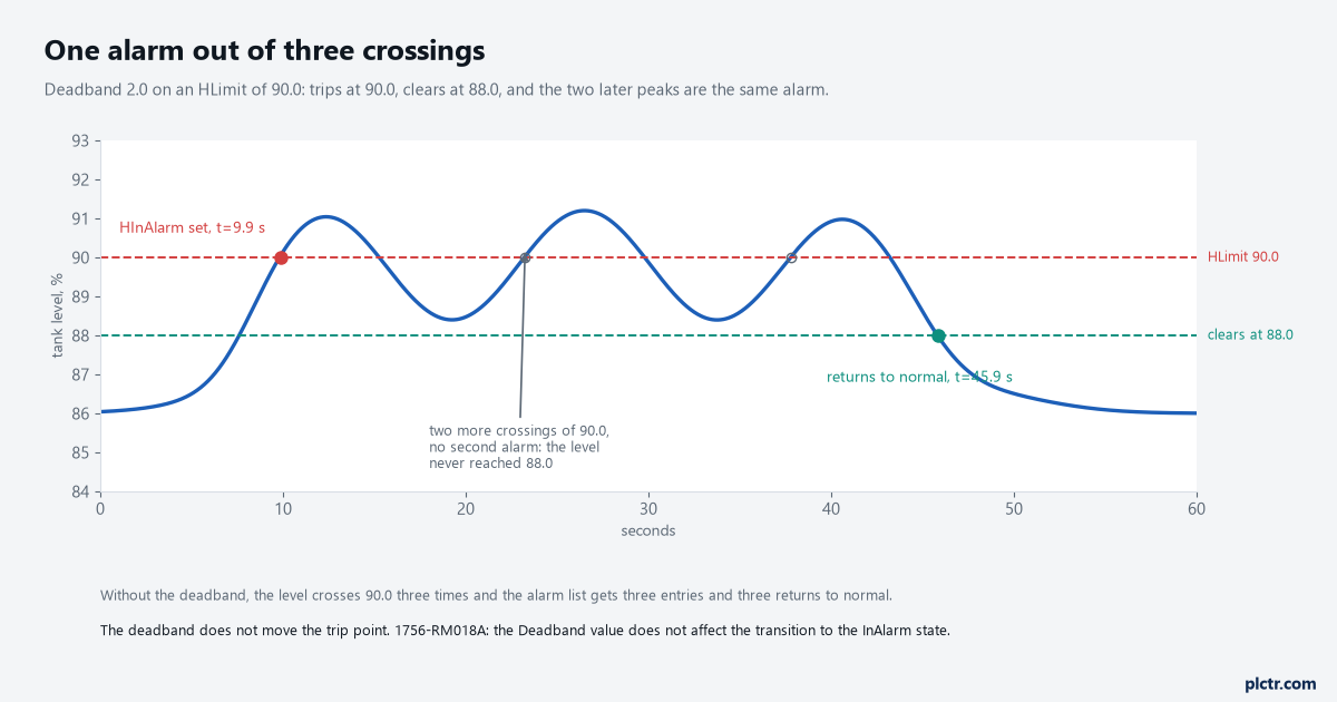
Three upward crossings of 90.0, one alarm. HInAlarm sets at 9.9 s and the condition returns to normal at 45.9 s, because between those two moments the level never got as low as 88.0.
Acknowledging from two places, and the button that does not work
Every operation on these instructions exists twice: a Prog version your logic writes and an Oper version the HMI writes.
The pairs are ProgAck/OperAck, ProgReset/OperReset, ProgSuppress/OperSuppress, ProgShelve/OperShelve and so on, and the two differ in who clears them. The instruction clears the Oper parameters itself after acting on them; the Prog parameters are copied from the instruction operand and require a false-to-true transition, so a ProgAck held true acknowledges once and then never again. That edge requirement produces one specific, documented and genuinely confusing symptom when an operator holds a physical push button wired to OperShelve: because the ProgUnshelve tag takes precedence and program scans complete in milliseconds, the button can still be held down after ProgUnshelve has gone false, the transition the instruction needs never happens, and the alarm is not shelved. The manual’s own fix is to release the button and press it again, and the detail is written up in full in connecting a button to the OperShelve tag.
On a CompactLogix 5380, ControlLogix 5580 or ControlLogix 5590 there is a fourth instruction worth knowing about.
ASO, Alarm Set Operation, issues one operation — Acknowledge, Reset, Enable, Disable, Unshelve, Suppress, Unsuppress or ResetAlarmCount — to every alarm condition in a named alarm set, and it reacts to the false-to-true edge of its own .EnableIn rather than to the level, using a .LastState member to remember. It is the right answer to “acknowledge everything on this machine” and the wrong answer to anything that needs to know which alarm it acknowledged. The warning printed with it is worth respecting: if any of its configuration operands change in Run mode you have to accept the edits and cycle the controller from Program to Run for them to take effect, and if the alarm set is large the execution time of the instruction can increase significantly. There is more on it in the ASO instruction, and the older walk-through of the analog instruction on its own is in PLC analog alarm ALMA.
What to check first
Put Status on a watch window before you touch a limit. Four of its bits — SeverityInv, AlarmLimitsInv, DeadbandInv and the two ROC ones — are the difference between an instruction that is working and an instruction that has silently fallen back to a default, and none of them raises a fault. AlarmLimitsInv is the one to look at first, because it is the only one that stops detection altogether.
Then read the rung. If there is a contact in front of an ALMD that is not the alarm condition itself, it is not disabling the alarm, it is clearing it, and the return-to-normal in the alarm history is fiction. Move that logic to ProgDisable and the history becomes worth keeping. If the alarms are going to a FactoryTalk View SE server, the subscriber end has its own configuration to get right, and the HMI setup is where that side starts.