Registration and the MAR Instruction: Catching a Mark at Speed on a Kinetix 5700
A Kinetix 5700 inverter latches a registration event with ±3 µs accuracy and 700 ns repeatability, and its propagation delay is compensated to zero. At 1.5 m/s that accuracy figure is 4.5 µm of position uncertainty. The photoeye in front of it, on a datasheet that says 1.2 ms, contributes 1.8 mm.
So the useful question about registration is almost never about the drive. Getting a mark caught properly on a Logix axis comes down to three things: the sensor’s own response time, whether the MAR instruction was armed when the mark went past, and whether the position you latched is in units that mean anything. The drive is the only part of that chain doing its job in microseconds.
Measure the sensor before you argue about the encoder.
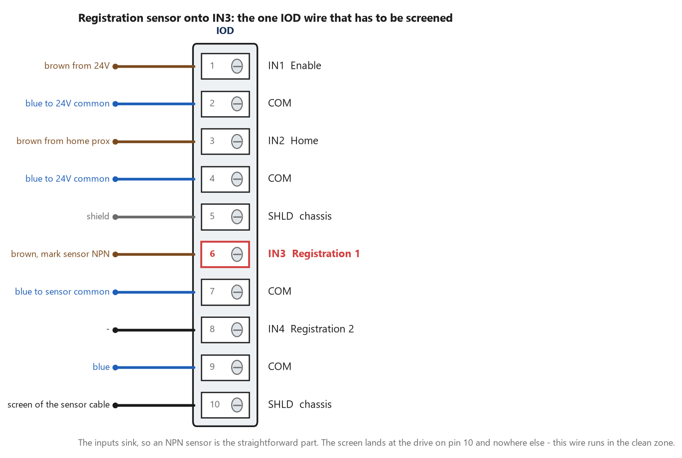
The registration wire is the one IOD conductor the Kinetix 5700 manual puts in the clean zone and asks for screened cable on. Every other dedicated digital input is in the dirty column.
What MAR actually does
Executing an MAR arms registration event checking on one axis, on one of the two registration inputs, for one edge. When the selected input makes the transition you asked for, the drive computes where the axis was at the instant of the event from hardware-latched encoder count data, writes it into Registration1Position or Registration2Position in the axis structure, sets the instruction’s .PC bit and sets the matching RegEvent1Status bit. The operands are worth knowing in order, because the Parameter Out of Range extended error code is the operand’s index counted from zero rather than an enumeration — so an extended code of 4 is the Min Position value, not an error number you can look up. Those operands are Axis, Motion Control, Trigger Condition (0 for a positive edge, 1 for negative), Windowed Registration, Minimum Position, Maximum Position, Input Number. In Structured Text that is MAR(Axis1, MAR_1, Positive_Edge, enabled, minmarpos_1, maxmarpos_1, 1); and the last operand only ever takes 1 or 2. Two other rules constrain the design: multiple registration events can be active at once on an axis, but only one per registration input, and the axis must be configured as Servo or Feedback Only or the instruction errors outright. The positions themselves come back in the axis’s configured Position Units, which means an axis that was never scaled in real units hands you a registration position in motor revolutions and a print-mark correction that is wrong by the gearbox ratio. There is also a Registration1Time attribute carrying the lower 32 bits of CST time in microseconds at which the event happened, which is the better thing to use when you are correlating a mark against something else on the network rather than against the axis itself.
Two inputs, two positions, two independent status bits. One event each.
The error budget, and where the drive is barely in it
The reference manual gives the arithmetic in one line: the uncertainty in a registration position is the distance the axis travels during the delay in recognising the transition, and it puts that delay at typically 1 µs for hardware registration. The Kinetix 5700 specification is in the same territory — ±3 µs accuracy, 700 ns repeatability — with two numbers alongside it that matter more than they look. Propagation delay for the registration functions is listed as 0, delay compensated, which means the drive is correcting for its own input circuit rather than leaving you to. And pulse reject filtering on a registration input is 12.0 µs, against the 20 ms nominal debounce applied to every other input function on the same connector. A mark that is present for less than 12 µs will not be seen at all; at 1.5 m/s that is a mark under 18 µm wide, so the filter is not the constraint in any real application. Then there is the sensor. A general-purpose diffuse photoeye with a 1.2 ms response is nearly three orders of magnitude slower than the latch, and at line speed that gap is the entire error. Rearranging the same formula the other way gives you the useful number: for 0.5 mm of registration accuracy at 1.5 m/s, the sensor has to respond inside about 330 µs.
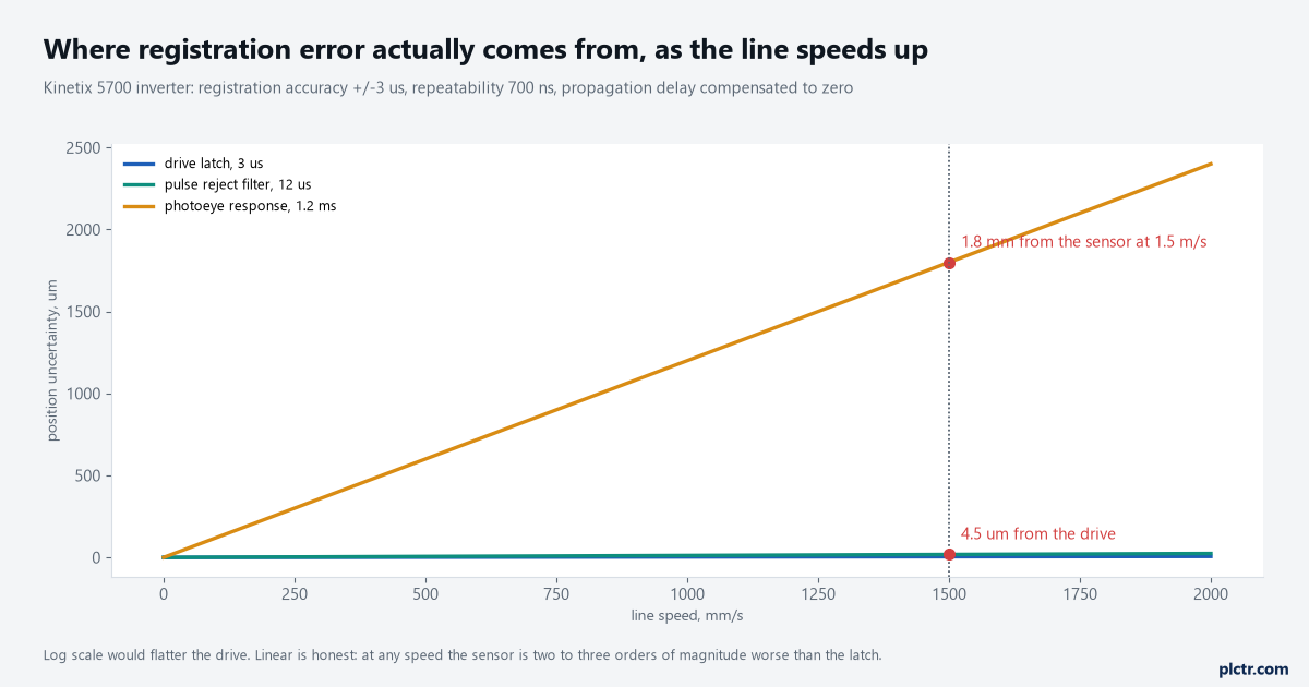
Linear axes, deliberately. A log scale would flatter the drive and hide the only line on the chart you can do anything about.
This is the dead end worth naming. An engineer with a registration that wanders by a millimetre reaches for the encoder resolution, or the drive firmware, or the motor feedback type, and all three are already three orders of magnitude better than the thing that is actually moving. Put a scope on the sensor output and the drive’s own registration status bit at line speed, and the shape of the problem stops being a guess.
The drive contributes microns. Everything else in the chain contributes millimetres.
Rearming, and the marks you never saw
MAR is a transitional instruction, so the rung has to go from false to true again before it arms a second time, and how fast that happens depends on the program scan time and the motion task’s coarse update rate. Write the rearm the obvious way — one rung executing MAR on XIC Reg_Arm, a second rung unlatching Reg_Arm when MAR_1.PC appears, and a third setting it again — and on an 8 ms periodic task with a 2.0 ms coarse update period you have about 14 ms between the event and being armed again. At 1.5 m/s that is 21 mm of product going past blind, which is fine for cartons at half-metre pitch and hopeless for a labelling head. The tighter pattern is one rung: condition the MAR on XIO MAR_1.IP alongside whatever your run permissive is. The instruction sets .IP on execution, which makes its own rung false; the event clears .IP, which makes the rung true at the next scan and rearms it. That halves the blind window without any extra logic. The reference manual adds one more thing to check on a busy controller, which is that force values in large I/O connections can slow the rate at which the controller processes repetitive motion registration — worth remembering if the registration got worse the day somebody left a force on.
.DN is not immediate either. The request needs several coarse updates to complete.
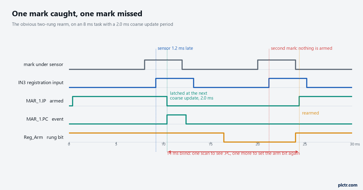
Drawn from the two-rung rearm described above. The first mark is caught cleanly; the second arrives during the two scans it takes to cycle the arm bit and is never recorded.
Windowed registration, and the marks you do not want
Setting the Windowed Registration operand to 1 makes the instruction accept a registration event only if the computed position falls between the Minimum and Maximum Position values. What happens to the events outside that window is the part worth knowing: registration event checking is automatically rearmed, inside the drive, with no rung transition and no scan cost. So a window is the correct answer to a sensor that also sees a seam, a splice or a reflection — far better than filtering the same nuisance transitions in ladder, where every rejected event costs you the rearm time from the section above. On a linear axis the values can be positive, negative or mixed, but Minimum has to be less than Maximum or no event is ever accepted. On a rotary axis both values have to be below the unwind, and Minimum may deliberately be greater than Maximum, which is how you write a window that straddles the unwind point. The Kinetix 5700 specification puts one number on this: the windowed registration invalid-to-valid event delay is 125 µs minimum, so two marks either side of a window boundary closer together than that are not separable.
MDR, Motion Disarm Registration, is the other half of the pair, and it is the right instruction for ending registration at the end of a product run rather than leaving an armed event and a stale RegEvent1Status bit for the next operator to interpret. Where the latched position goes next is usually a phase correction on a geared or cammed axis, and that correction has its own failure modes — see MAG and gearing two axes.
Windowed rejection is free. Rejecting the same event in ladder costs you a rearm.
What to check next
Trend Registration1Position against the position the machine expected, over a couple of hundred marks rather than ten, and look at the shape of the scatter rather than its width. A constant offset is a sensor mounting or a fixed delay and it corrects out. A scatter that grows with line speed is a response-time problem and no amount of logic will fix it. A scatter that is tight for most marks with occasional large outliers is a nuisance trigger and belongs in a registration window. And if the marks themselves are arriving with inconsistent spacing, the problem is upstream of registration altogether — that is a product-tracking question of the kind covered in tracking a carton through four zones and in gapping cartons before a scanner. For an axis that has not run yet, registration is a long way down the list: the order of the earlier jobs is in driving a motor from a ControlLogix.