THRSe, TSAM and FSBM: The Four Sensors and the Sequence That Has to Hold
An FSBM instruction sitting at Fault Code 16#9121 has already told you where to look, and it is not a sensor alignment problem yet. The third digit of that code is the step number: the instruction was in step 2 of its muting sequence when an input transition arrived that step 2 does not allow. Codes in the 16#9100 to 16#9196 range are all shaped that way, one block of seven per step from step 0 to step 9, so 16#9100 through 16#9106 is step 0, 16#9110 through 16#9116 is step 1, and so on. That is worth more than the sensor LEDs, because it says which transition the instruction was waiting for when the wrong one turned up. This article is the three instructions whose safety comes from order and timing rather than from a level — THRSe for a two-hand run station, TSAM for a two-sensor mute and FSBM for a four-sensor one — and it is 1756-RM095O, September 2025, throughout.
None of these instructions decides where a sensor goes. That comes out of the risk assessment for the material, and nothing below changes it.
Reading the code before you move anything
Four families of FSBM fault code, and they point at four different kinds of problem.
A code starting 16#92 is an illegal input pattern: a static combination of the five inputs that cannot happen if the sensors are aimed where the drawing says, and the manual lists them individually from 16#9200 to 16#9215 with a column per input showing which were blocked. 16#9201, for instance, is all four sensors blocked with the light curtain clear, which on a real conveyor usually means a sensor is looking at the frame rather than at the load. A code starting 16#91 with a digit in the third position is the sequence code described above, and 16#91A0 and 16#91A1 are the special case of the first sensor blocked disagreeing with the Direction input, which is not a sensor problem at all but a Direction bit driven from the wrong piece of standard logic. Codes 16#9010 to 16#9013 are the four timers expiring, one each for S1-S2, S2-LC, LC-S3 and S3-S4 in that order, and 16#9000 is the separate Maximum Mute Time. And 16#20 is not about muting: the Input Status input went from on to off, so it is the I/O connection. TSAM has the same shape with different numbers — 16#96xx for the static patterns, 16#95xx for the sequence, 16#9410 to 16#9413 for its two timers in both directions, and the same 16#9000 for maximum mute time.
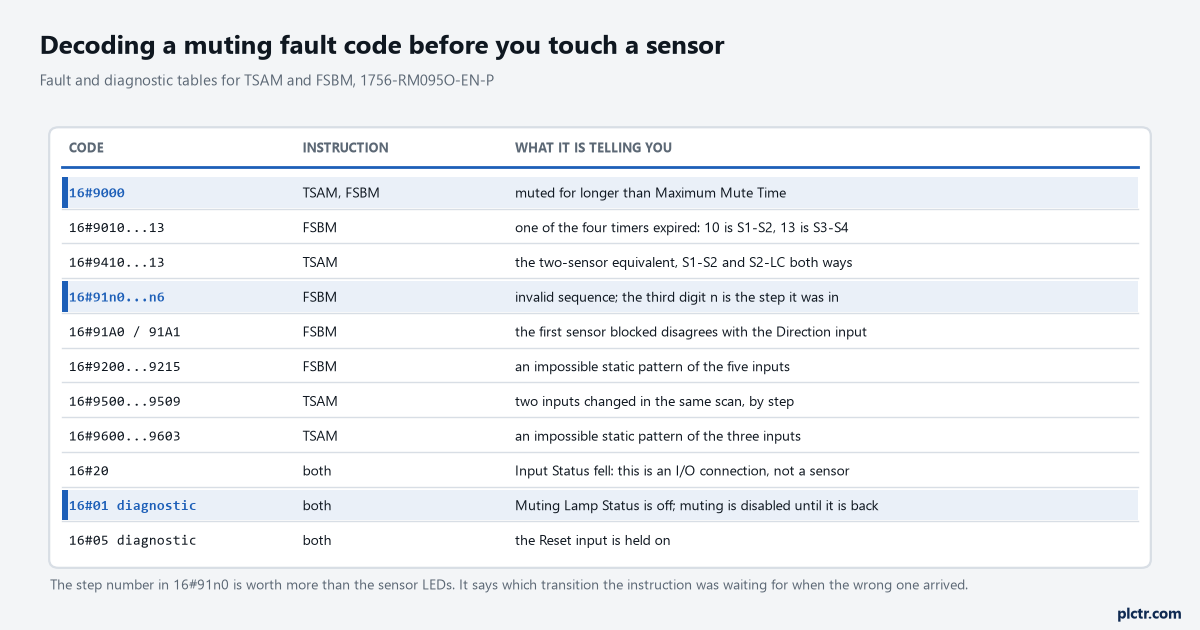
The static-pattern codes and the sequence codes look similar and mean opposite things. One says the inputs cannot be in that combination at all; the other says the combination is fine but arrived at the wrong moment.
The order FSBM insists on
Four sensors, two before the curtain and two after, and one Direction bit that says which end the material comes from.
With Direction at 1, the forward sequence starts when Sensor 1 is blocked and that starts the S1-S2 timer; Sensor 2 blocking stops it and starts both the S2-LC timer and the Maximum Mute timer, and the Muting Lamp output turns on at that moment; the light curtain blocking stops the S2-LC timer and starts LC-S3; Sensor 3 stops that and starts S3-S4; and Sensor 4 stops the last one. Then the material clears the sensors and the curtain in the same order it blocked them, running the same timers again, until everything is clear. With Direction at 0 the whole thing runs from Sensor 4 inwards. Each of the four timers takes 5 to 180,000 ms, which is three minutes at the top end and is there for slow pallet lines, and each of them accepts 0 to switch that particular check off. The instruction tolerates one thing deliberately: a sensor that glitches off and back on because of over-travel or load vibration does not fault it, provided the final input sequence is still valid, which is what stops a bouncing pallet stopping the line. Anything else is an invalid sequence, Output 1 drops, Clear Area comes on, and the material has to come out of the sensing field before the line can run again.
Clear Area is the output to put on the HMI. It names the job the operator has to do next, and getting a loaded conveyor moving again afterwards is its own problem.
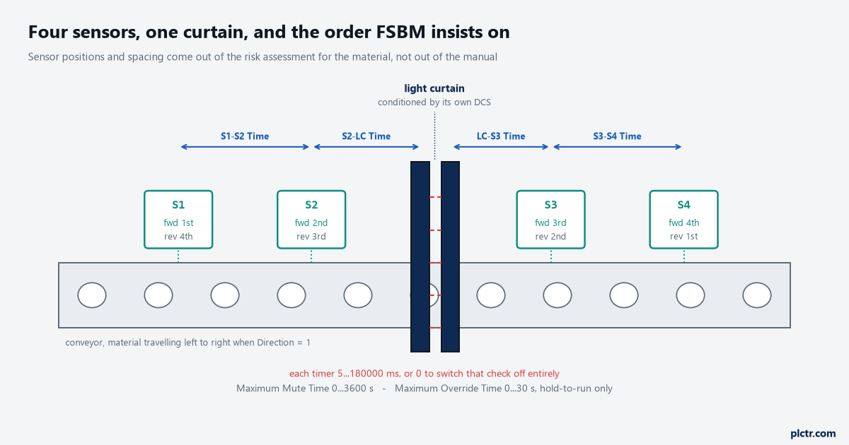
The sensor spacing in this drawing is illustrative. The real spacing is set by the material’s size, shape and speed, and by the assessment that says a person cannot walk the same pattern.
The light curtain input is not the curtain’s OSSD pair. It is a conditioned signal, and the instruction reference says to produce it with a DCS instruction controlling the light curtain, whose Output 1 then feeds the muting instruction. Get that wrong and the muting instruction sees the curtain’s own pulse tests as blockages.
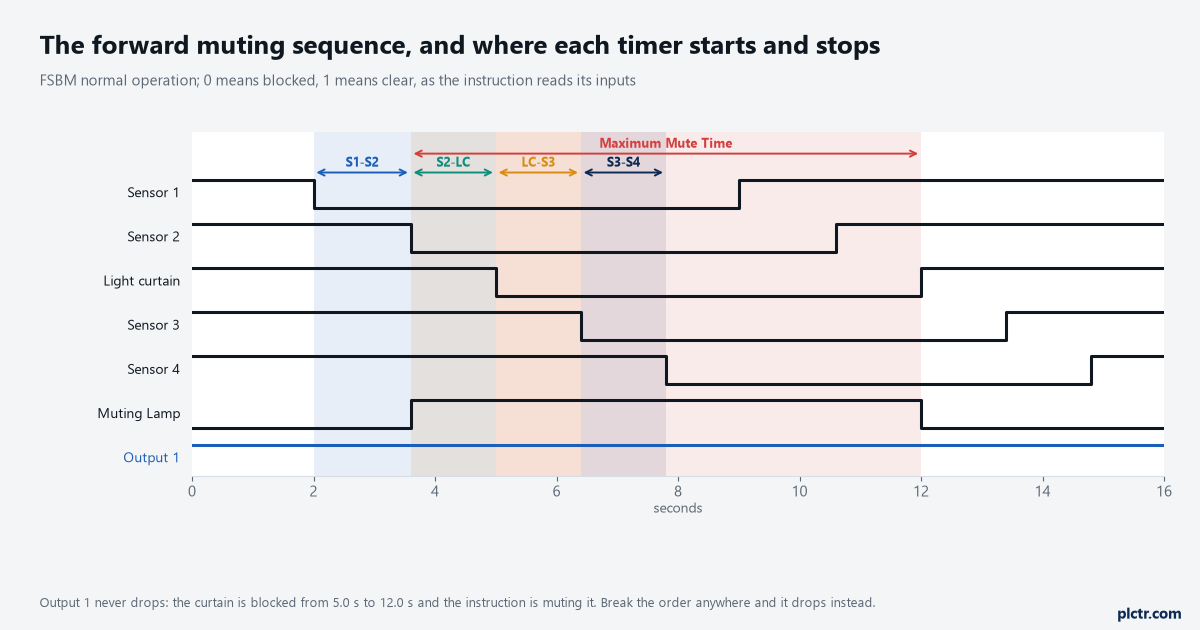
Drawn from the instruction’s own normal-operation narrative, which names the timer that starts and stops at every transition. Worth reading against your own trend, because the operand table and the fault-code table describe two of these timers using “cleared” where the operand definition says “blocked”; the timing diagram is the unambiguous one.
TSAM is the same idea with two sensors arranged asymmetrically on either side of the curtain, intersecting just behind it. Sensor 1 must be the first blocked and the last cleared, Sensor 2 the second blocked and the first cleared, and the two timers are S1-S2 and S2-LC with the same 5 to 180,000 ms range. Fewer sensors is fewer things to align and fewer ways to get the sequence wrong; it is also fewer constraints on what a person could do, which is a matter for the assessment and not for the instruction.
Muting is one of the functions a relay cannot give you, and one of the honest reasons to move to a safety controller rather than a bigger relay.
THRSe: the 500 ms nobody can change, and the one they can
Two buttons, four contacts, and two completely separate time windows that people routinely confuse.
The 500 ms is between the buttons: both have to be pressed within half a second of each other for Output 1 to energise, and it does so 50 ms after the second press. That number is fixed in the instruction. The Discrepancy Time operand, with its range of 100 to 3000 ms, is about one button’s own two contacts, because each button brings a normally-open and a normally-closed contact and they are inconsistent when both read the same logical value, which is the same measurement problem as any dual-channel device; fault codes 16#7001 and 16#7002 name the right button with which contact was on, 16#7003 and 16#7004 do the same for the left. Then there is a constraint that lives nowhere near either operand, and it is the reason to read this article next to the safety task period: for the 500 ms to be detected properly, the instruction reference states that the safety task period cannot exceed 40 ms and the input device’s requested packet interval cannot exceed 20 ms. A project that has stretched the period to 50 ms to fit a large routine has broken its two-hand station, and nothing in the THRSe operand list will say so.
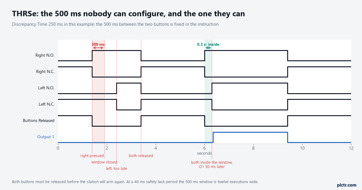
Once one button has been held alone past 500 ms, pressing the other does nothing. Both have to be released before the station will arm again.
The disconnect feature is worth knowing before somebody unplugs the station. To bypass it properly the Disconnected input has to be on and all four button inputs off, and then Station Bypassed comes on; do it in the wrong order and you get 16#7030, which says the Disconnected input was on while the button inputs were not all off. Reconnecting is the mirror image. Neither is a fault in the wiring, and both produce a call.
Disconnect it in the wrong order and the code is 16#7030, not a broken plug.
Zero is not a smaller number
Every one of these timers accepts 0, and 0 does not mean fast. It disables that check.
Setting S1-S2 Time to 0 removes the constraint that Sensor 2 has to be blocked within a sensible time of Sensor 1, which is precisely the constraint that distinguishes a pallet moving at line speed from a person walking through. Maximum Mute Time at 0 removes the limit on how long the curtain may stay muted, so a load stopped in the sensing field by an upstream jam keeps the curtain muted indefinitely. Maximum Override Time at 0 removes the limit on the override, which is already the most dangerous input on the instruction: the override energises Output 1 regardless of Input Status and regardless of whether faults exist, and the manual carries a warning that it may be used only with a hold-to-run device positioned where the operator can see into the sensing field. The Muting Lamp Status input belongs in the same paragraph, because when it reads off the instruction treats the lamp as defective or missing and keeps the curtain’s protective function enabled; if your application genuinely has no muting lamp, that input is tied on deliberately, and that is a decision somebody signs rather than a default somebody leaves. Enable Mute works the same way: off means the curtain always protects, and if there is no part of the cycle where material must not pass, the manual’s own advice is to hold it at a constant on rather than leave it floating.
A timer set to 0 to stop nuisance faults has removed a safety function. Say so out loud before you do it.
What everybody does first
Realigns a sensor. It is the visible part of the system and it is sometimes right.
Read the code first, because three of the four families do not point at alignment at all. A 16#91A1 says the Direction input disagrees with reality, and moving sensors will never fix a bit driven from the wrong conveyor-running tag. A 16#9010 says the S1-S2 Time is too short for the gap between those two sensors at this line speed, or that Sensor 2 has a problem, and the fix might be a number rather than a bracket — though a number changed to make a fault go away is a number that needs justifying against the assessment, not just against the downtime. A 16#20 is the I/O connection. Only the 16#92 family reliably says a sensor is seeing something it should not, and even there the first question is what changed about the material, not about the sensor. If the line has started running a different pallet, the sequence and the timings were set for the old one.
Next step
Get the fault code and the diagnostic code out of the instruction’s backing tag and onto the HMI, as two separate numbers with the step decoded into words — “invalid sequence, step 2” reads better at 3 a.m. than 16#9121. Then take the four timers and write next to each one the measured time for the slowest load you actually run and the fastest, because those two numbers are what the setting has to bracket, and neither of them is in any manual. Check the safety task period against the 40 ms ceiling if there is a THRSe anywhere in the project. And for the part that no instruction covers — whether a person can reproduce the material’s switching sequence and walk in — that is a hazard and risk assessment of your own application, done by people qualified to do it, and it has to be validated on the machine rather than reasoned about from a drawing.