A new SM 1223 goes into slot 2, the panel comes back up, and the ERROR LED flashes red while the STOP/RUN LED sits solid yellow. The module that came out was 6ES7223-1BL32-0XB0. The one from stores is 6ES7223-1BL32-1XB0, and those two part numbers are the same sixteen inputs and sixteen outputs in the same 70 mm housing, differing in the one character that decides whether the outputs source or sink.
The CPU is telling you which of three things is wrong and the manual limits it to three. A flashing red ERROR means an internal CPU error, a memory card error, or a configuration error, and the manual names mismatched modules in that last bracket. After a module change it is the third one nearly every time. The next thing to look at is the module’s own DIAG LED, not the laptop.
All the LED states and startup settings below come from the S7-1200 system manual, edition V4.6 of 11/2022. Where something is what I observe rather than what the manual prints, the sentence says so.
Two LEDs, in the order that matters
Take the CPU first, because the combination of its three indicators is a lookup, not a judgement call. STOP/RUN solid yellow is STOP and solid green is RUN, while the two colours alternating means startup, a self-test or a firmware update. ERROR flashing red is the error state, and the manual’s table pairs it with a STOP/RUN LED that can be either yellow or green, so the CPU may well still be running while it flashes at you. ERROR flashing red for three seconds and then stopping is a different animal: the manual calls that an error that is not ongoing and gives the real-time clock resetting to its default after a power loss as the example, which is exactly what you get on a panel that has been off for a month. ERROR solid red with STOP/RUN solid yellow is defective hardware. All three LEDs flashing together is the firmware reporting a defect. STOP/RUN solid yellow with both ERROR and MAINT flashing is its own entry, an unknown or incompatible version of CPU configuration, which comes from loading an invalid project such as a V3.0 program into a V4.x CPU, or from a mismatch in the protection of confidential configuration data.
Flashing red at the CPU, then the module. That order, because the module tells you which one.
The signal module has one DIAG LED and three states that matter. Solid green says the module is configured and has no faults. Flashing green says it is not configured, or an update is in progress. Flashing red is an error condition. On an analog SM only, DIAG and the channel LEDs flashing red together means the field-side power is off, and the manual flags that status as supported on analog modules only.
So the pair you want after a swap is ERROR flashing on the CPU and DIAG flashing green on the new module. That combination says the module is physically alive, is talking to the backplane, and is not the module the project expects.
Alive on the backplane, wrong in the configuration. That is what the pair is saying.
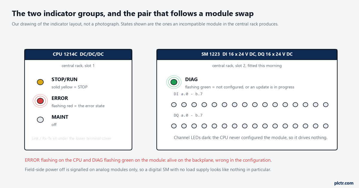
Our drawing of the indicator layout, not a photograph. The pair that matters after a module change is ringed: ERROR on the CPU, DIAG on the module.
Why compatible is not the same as identical
The startup properties of the CPU carry a parameter named comparison of preset to actual configuration, and it has two settings: startup of the CPU only if compatible, and startup of the CPU even if there is a mismatch. The manual’s definition of compatible is tighter than the word suggests and it is worth quoting in shape rather than in words: the module sitting in the configured slot has to match the configured module in its number of inputs and outputs and in its electrical and functional properties, and it may be more capable than the configured one but never less. A sinking output stage against a configured sourcing output stage fails that test on electrical properties while passing it on channel count, which is why the two SM 1223 variants above are such a clean trap. Both are DI 16 x 24 V DC, DQ 16 x 24 V DC. Both take 20.4 to 28.8 V DC on the outputs. The spec table separates them on one row: the -0XB0 outputs are solid state MOSFET sourcing and the -1XB0 outputs are solid state MOSFET sinking.
Same footprint, same channel count, opposite output stage. The label is the only place it shows.
What happens next depends on where the module is. The manual’s pull-or-plug chapter lists the conditions that raise the event, and an incompatible module in a rack that does not correspond to the configured module is one of them. For distributed I/O with no OB written, the CPU stays in RUN. For a module in the central rack the CPU changes to STOP whether or not the OB exists, which is what puts STOP/RUN on solid yellow while ERROR flashes.
Central rack means STOP. There is no OB you can write that changes it.
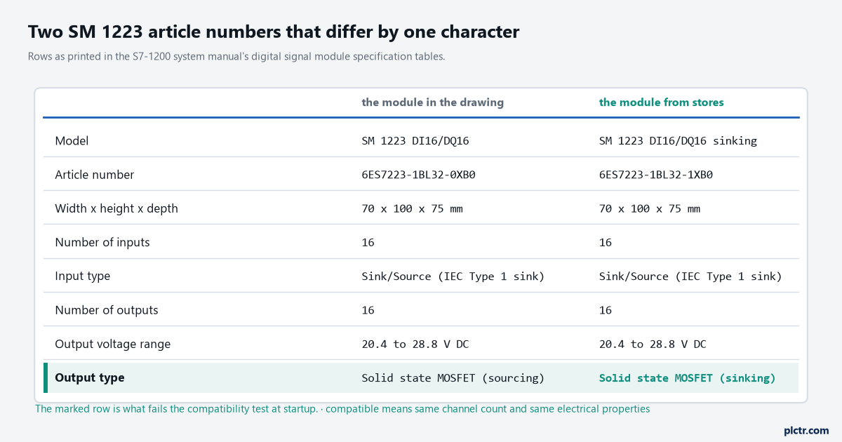
Rows from the digital signal module specification tables. Everything matches until the output type, and that single row is what fails the compatibility test.
The dead end everybody walks first
Before the article numbers get compared, the module comes out and goes back in, the terminal block gets unplugged and replugged, and somebody measures 24 V at the field terminals. All of that is reasonable and none of it is the fault here, because a module that is seated badly does not flash DIAG green at you, it goes dark or the CPU reports it missing entirely. Field-side power is the other reflex and it is worth knowing why it misleads on a digital module: the manual only supports the field-side-power-off indication on analog signal modules, so a digital SM 1223 with no load supply flashes nothing special and simply reads its inputs as zero and drives nothing. Two engineers can spend half an hour on the wiring of a module that is wired correctly.
A badly seated module does not flash DIAG green, so the seating was never the problem.
Read the article number off the module label first. It takes ten seconds and it settles the question.
The other honest dead end is the diagnostics buffer, which is the right tool and the slow one. The buffer entry names the rack and slot and says what it found, and the same condition appears in the record-job decodes as a type conflict, error decode B#16#B3 or 80B3 in the extended-instruction tables, worded as the actual module type not matching the specified module type. Those particular codes are printed in the manual’s distributed I/O chapter, so treat them as the wording to expect rather than as a promise about a central-rack slot.
Reading the LED without a laptop
There is an instruction for this and almost nobody uses it. The LED instruction takes LADDR, which you fill from the drop-down as Local~Common for the CPU itself, and an LED identifier: 1 for RUN/STOP, 2 for Error, 3 for Maintenance. RET_VAL comes back as a state, and the state list is where the flash rate finally gets a number. 1 is off, 2 is colour 1 solid, 3 is colour 2 solid, 4 is colour 1 flashing at 2 Hz, 5 is colour 2 flashing at 2 Hz, 6 is both colours alternating at 2 Hz, 9 is a state that is not available. On the ERROR identifier colour 1 is red, so RET_VAL 4 is the flashing red this article is about, measured rather than described. The error returns are equally plain: 8091 for a device that does not exist at that LADDR, 8092 for a device with no LEDs, 8093 for an identifier that is not defined, and 80Bx for a CPU that does not support the instruction.
Two Hz. That is the rate, from the instruction’s own state table.
Put that value on an HMI line during commissioning and the maintenance call changes shape, because the person on the phone can read you a number instead of describing a colour. It costs one instruction and one Int.
Add it to the diagnostics screen once and it earns its place for the life of the panel.
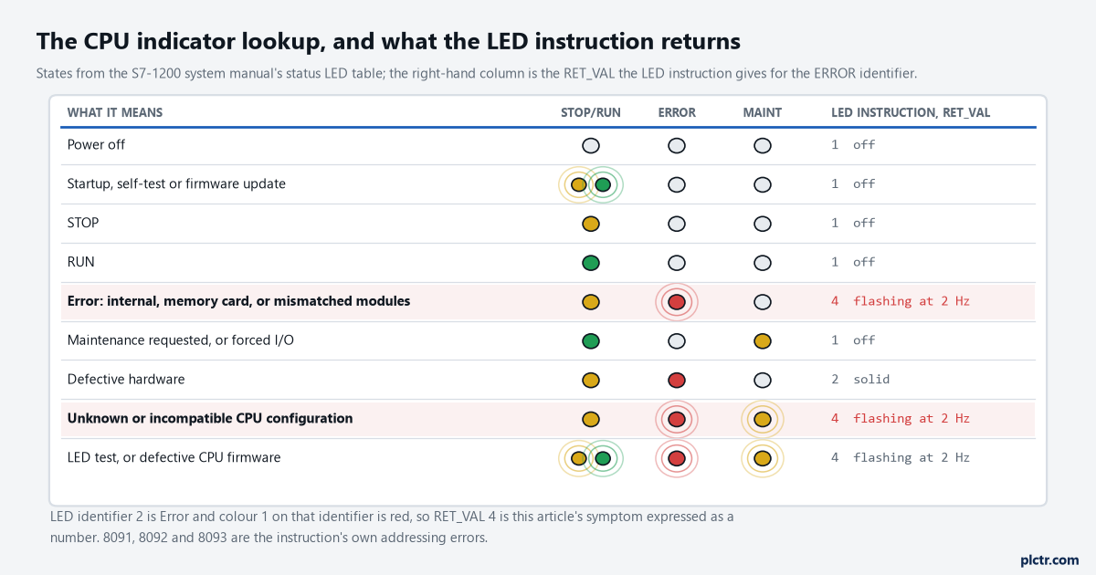
The manual’s own LED table, redrawn. The two highlighted rows are the ones a module swap produces, and the right-hand column is what the LED instruction returns for each.
Fixing it, and the setting that only looks like a fix
The repair is whichever of two things is true. If the project is right and the module is wrong, fit the article number the project asks for, and do not let anybody talk you into rewiring the field side to suit the module that arrived. If the module is right and the project is old, open the device configuration, right-click the module, use Change device, and pick the article number that is actually in the rack, then compile and download. Hardware detection will read the rack back for you when the project has drifted further than one module, and the manual’s own warning goes with it: download the detected configuration before you go online again or an inconsistent configuration will produce its own error.
Changing the startup parameter to start even on a mismatch is not a repair. It is a decision to run with outputs that behave differently from the drawing.
That setting has a legitimate use, and this is not it. The same startup page carries a configuration time with a default of 60000 ms for the central and distributed I/O to come up, and the CPU goes to RUN as soon as they are ready rather than waiting the whole time out. A slow remote station is what that parameter is for, and a wrong module is not a slow one.
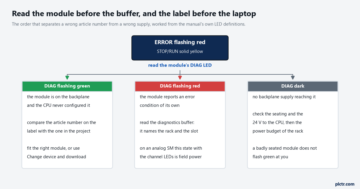
The order to work in. The left branch is the module swap this article covers; the other two go to the buffer and to the supply respectively.
What to do before the next module comes out of stores
Photograph the label before the old module leaves the rack, because the article number is the thing you will want at 22:00 and it is the thing nobody writes down. Keep the spares list in the project file with the full article number rather than the family name, so SM 1223 DI16/DQ16 never gets ordered again without the last four characters. When the download is done and the module is accepted, check that DIAG is solid green rather than assuming it, and keep an eye on the firmware question separately, since a mismatch there produces a different failure that is covered in why an S7-1200 download stops on a firmware mismatch. If the replacement is a newer article number that the catalogue does not offer you, the missing support package is a known and separate problem, worked through in getting a new device into the hardware catalog. And if the sourcing and sinking distinction above is the part that needs pinning down before the next order, sinking, sourcing and module keying covers it from the wiring end, while the S7 error code list is the faster place to decode whatever the buffer hands you.