The scope says twelve bays, a MiCOM C264 in each cubicle, a gateway to the control centre, and an SCD file that the protection engineer will issue in week six. There is no ladder anywhere in it, no tag database you recognise, and no download button of the kind you have been pressing for fifteen years. SAS is the acronym on the cover, and it stands for substation automation system.
Here is the shape of the thing before any of the names.
A substation automation system is the protection, control and monitoring stack inside one substation, from the instrument transformer secondaries up to the circuit that leaves for the control centre. It is usually described in three layers — process, bay and station — and the habits you brought from a PLC panel land on the middle one. IEC 61850 is not a fieldbus you pull into a duct; it is an agreed data model plus a set of configuration files, and an engineering tool turns those files into the mapping each device needs. On the Schneider side the catalogue splits into devices, station software, and the tools that configure both, and knowing which heap a name belongs to answers most of the questions a first project raises.
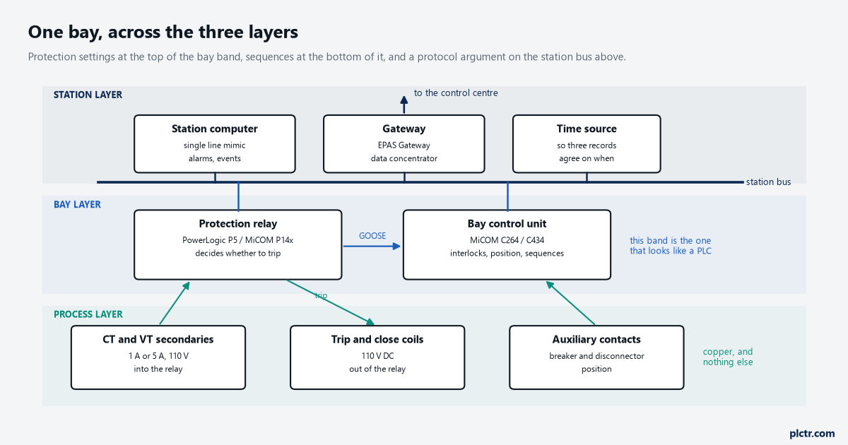
One bay, station layer at the top and copper at the bottom. The PLC engineer’s reflexes belong in the middle band; the top band is a communications contract with somebody else’s SCADA and the bottom band is instrument transformers and coils.
What SAS covers, and where your instincts land
Start from the switchgear and work up. At the lowest layer are the things with copper on them: current and voltage transformer secondaries, the breaker trip and close coils, auxiliary contacts that say whether a disconnector is open, and the interposing that keeps 110 V DC away from anything that does not want it. Above that sits the bay layer, where a protection relay decides whether to trip and a bay control unit handles interlocking, position, and the local mimic for the operator standing in front of the cubicle. Above that is the station layer: a station bus joining every bay, a gateway that speaks whatever protocol the control centre asked for, a station computer with the single line drawn on it, and a time source, because a disturbance record from three relays is only useful if the three agree on what time it was. The part that surprises people arriving from machine control is how much of the logic is not written by anyone. Protection functions are chosen and set, not coded. Interlocking is largely declared. What does get written, and this is the bay-layer work you will recognise, is the automation around all of that: auto-reclose sequences, tap changer control, load shedding, transfer schemes, and the interfacing that makes a diesel start when it should.
Three layers, and only one of them looks like a PLC to you.
Where IEC 61850 sits, and what it is not
Ask a PLC engineer what a protocol is and the answer involves registers, an address map, and a spreadsheet with somebody’s initials on it. IEC 61850 removed the spreadsheet and put a model in its place. Instead of agreeing that word 40017 carries breaker position, the devices carry a described model of themselves — what functions they contain, what data those functions expose, how each item is named — and that description travels as a file rather than as a phone call. The files are written in a configuration language the standard defines, and the one everybody names out loud is the SCD, the system-level file that holds the whole substation. Schneider’s own engineering tool describes its job in exactly those terms: it supports the standard from edition 1 through to edition 2.1, it integrates the individual device tools through that configuration language, and it produces the SCD so that the system keeps one description rather than twelve. It also imports GOOSE and sampled value data in bulk, which is the second thing worth understanding early. GOOSE messages are how one device tells the others on the station network that something has happened, without a wire between them for every signal, and sampled values carry measurement streams in the same style.
The standard names the model. It does not name your sequence, and nobody is going to write that for you.
So the mental shift is this. You are not going to map registers between a relay and a gateway by hand; you are going to be handed, or asked to produce, a system description that both of them are configured from. If you have spent years on which protocol to pick between a PLC and a SCADA system, the habit to unlearn is treating the point list as the deliverable. Here the model is the deliverable and the point list falls out of it.
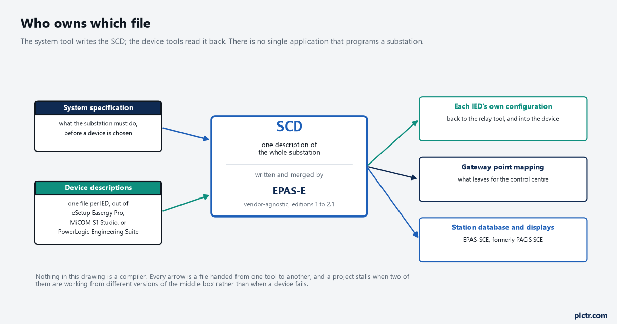
Every arrow in and out of the SCD is a file handover, and each one belongs to a different tool. The reason a project stalls is almost always that two of these are out of step, not that a device is broken.
Which Schneider box does which job
The catalogue reads as a wall of P-numbers until you sort it by layer, and then it is short. Protection relays are the bay-layer devices that decide to trip: the current families are PowerLogic P7, described as a modular platform with a seven-inch touchscreen and its own engineering tool, PowerLogic P5, which is the withdrawable medium-voltage range listed with LPCT and LPVT inputs, redundant Ethernet and IEC 61850, and PowerLogic P3, the compact medium-voltage range whose catalogue entry states plainly that it was formerly known as Easergy P3. Behind those sit the MiCOM families that are still all over existing substations and still listed: the Px40 series with P14x for feeder management, P24x for rotating machines, P34x for generators, P44x for distance, P54x for current differential, P64x for transformer protection and control, P740 and P746 for busbar protection, P841 for line terminals; the Px30 series with P13x feeder management and bay control, P43x distance, P53x line differential and P63x transformer differential; and the Px10 series where P115 and P116 are the self-powered or dual-powered overcurrent relays for a supply with no reliable auxiliary voltage. Sepam series 80 covers motors, generators, busbars, capacitors and transformers from a single range. Arc flash gets its own devices rather than being a setting on something else: the VAMP range runs from VAMP 120 up to VAMP 321, and PowerLogic A1 and A3 are the arc detection and mitigation units for enclosures. Two accessories are worth knowing by name before somebody asks you for them, because both turn up on drawings without explanation: MiCOM P849 is the digital input and output extension device for the MiCOM range, and the MiCOM P99x family is the test block and test plug set — P991 block, P992 plugs — that lets a technician inject secondary current into a scheme without unbolting it.
Controllers are the next heap, and this is where a PLC engineer is most at home. MiCOM C264 is the modular substation and bay controller that talks to the relays and to the local SCADA, takes in its own I/O and measurements, and runs automation; Easergy MiCOM C434 is the bay control unit for controlling and monitoring a bay; PowerLogic T500 is listed as a control unit and RTU for substation automation, aimed at connection to networks and enterprise systems on new or retrofit work; and SAITEL is the RTU and controller platform for the communication-heavy end of the job.
If you have wired a remote I/O drop and written the sequence above it, this heap is where you start.
Then the station software. EcoStruxure Power Automation System, usually shortened to EPAS, is the digital substation automation system itself — the station-level control and energy management layer. The EcoStruxure Power Automation System Gateway is the substation gateway and data concentrator, which is the box that owns the conversation with the control centre. EcoStruxure Cybersecurity Admin Expert is the configuration and policy tool for the operational technology side, and EcoStruxure System Management is the device management software that used to be called EPAS Maintenance, or EPAS-M.
Only one of those four is a box in the rack; the other three are software with licences and release cycles.
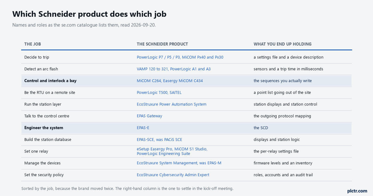
Sorted by the job rather than by the brand, because the brand moved twice. The right-hand column is the one to argue about in the kick-off meeting: whoever owns the SCD owns the schedule.
Three tools, three jobs, and none of them is Studio 5000
The question every controls engineer asks in week one is which piece of software programs the substation. There is no such piece of software, and the sooner that lands the better. The work is split three ways and each split has its own tool. System-level engineering — the specification, the device models, the communication mapping, the SCD — belongs to EcoStruxure Power Automation System Engineering, EPAS-E, which is described as vendor-agnostic and built for multi-vendor schemes rather than for Schneider devices alone; it also carries Modbus and IEC 104 alongside the IEC 61850 work, which is what makes an older relay fit into a new system. Station-level configuration — the database behind the station displays and the control logic that goes with it — belongs to the system configuration editor, EPAS-SCE, whose own catalogue entry is candid about its history: it is EcoStruxure Substation Operation SCE, and it used to be PACiS SCE. Device-level settings belong to the relay’s own software, and which one depends on the relay: eSetup Easergy Pro for the P3 range, MiCOM S1 Studio for the MiCOM families, and PowerLogic Engineering Suite for the newer work, which is listed as compliant with version 2.1 of the IEC 61850 standard and as integrating directly with EPAS-E.
That last sentence is the whole architecture in one line. The settings tool hands its device description to the system tool, and the system tool hands back what the device needs to know about everyone else.
Pick the wrong one and you will spend a fortnight producing a file nobody can use.
The names moved, and your search results did not
This is the practical trap on a first Schneider substation project, and it costs hours rather than minutes. Easergy P3 is now listed as PowerLogic P3, with the old name only as a parenthetical. PACiS SCE is now EcoStruxure Substation Operation SCE and is sold as EPAS-SCE. EPAS-M is now EcoStruxure System Management. The hardware in the cubicle did not change when the label did, so a search for the name stencilled on the relay in front of you lands on decade-old forum threads and on documentation the current catalogue no longer indexes under that name. Work in both directions: find the current product page from the old name before you start reading, and note the old name in your own project file so the next person does not repeat the search.
A device whose name has changed twice has documentation in three places.
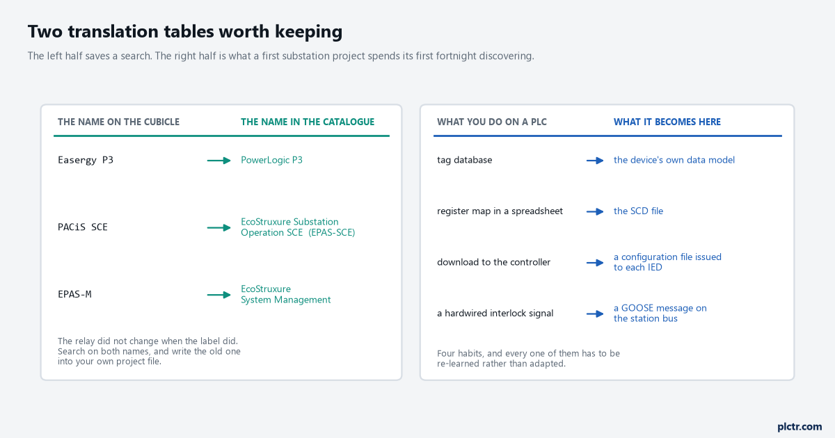
The left half saves you a search. The right half is the translation table worth writing on the inside cover of the project folder, because every one of those four habits has to be re-learned rather than adapted.
What to get hold of before you quote anything
Ask for the single line diagram and the point list the customer already has, and ask who owns the SCD. Those two answers decide more of the job than the device list does, because a project where the protection contractor issues the SCD and a project where you issue it are different pieces of work at different prices. Find out which edition of IEC 61850 the existing devices support, since an installation with a mix of edition 1 and edition 2 devices is a normal condition and not a defect. Then check what the control centre expects on the outgoing link, because that is a separate protocol decision from anything happening inside the substation.
If the wider electrical side is the unfamiliar part rather than the communications, permissives, synchronising and load shedding from a PLC covers the logic you will be asked to write at the bay layer, what SCADA is sets out the layer above, and the station bus itself is an Ethernet network with the same failure modes as any other, which is switches, VLANs and rings all over again with a substation-grade enclosure around it.