Four guard doors on a packing cell, a Trojan T15 tongue switch on each, 440K-T11390, all four pairs of contacts daisy-chained into one 440R-D22R2 relay, and the calculation for that stop function will not go past PL c. Every switch in the chain has its two direct-opening N.C. contacts, the wiring matches the drawing, and the required level from the risk assessment was d. The level was not lost in the panel. It was lost in the arrangement, in what the relay can still tell you about four devices once they share two wires.
A performance level belongs to a safety function, not to a part. The stop function that starts at those doors runs through three subsystems — the devices, the logic, the contactors — and the input side contributes three numbers to it: how many operations the device survives before it fails to a dangerous state, whether one fault in it can be tolerated, and how much of what can go wrong is actually detected. Daisy chains only damage the third one, which is why they look harmless on a drawing and cost you a level in the arithmetic.
Everything below is a guard interlock feeding a Guardmaster relay, with the numbers from Rockwell’s own publications.
What actually carries the performance level
The switch is a component with a capability; the safety function is what gets rated.
Machinery SafeBook 5 puts it plainly: an interlock switch rated to Category 1 can be used on its own in a Category 1 system, and the same switch forms part of a Category 3 or 4 system when two of them are used with a diagnostic function provided by a monitoring safety relay. So “is this switch PL d?” is the wrong question in the same way “is this fuse 30 A?” is the wrong question about a feeder. The input subsystem’s contribution is mean time to dangerous failure per channel, which the standard bands as low from 3 to 10 years, medium from 10 to 30, and high from 30 to 100 with 100 years as a hard cap no matter what the calculation produces; the architecture, which for PL d in a Category 3 arrangement means a single fault does not lose the function; and the diagnostic coverage the logic can actually achieve over the device. Common cause failure sits underneath all of it and has to score at least 65 points against the checklist in Annex F of ISO 13849-1 before any of the rest counts.
Three numbers, one function, and the switch supplies only part of one of them.

The performance level is calculated across all three blocks. Swapping the device changes one column of one block, which is why a better switch on its own rarely moves the result.
The device: two contacts, or one that watches itself
There are two honest ways to get a guard input to PL d and they want different things from you.
The mechanical path is a positively driven tongue switch with redundant contacts. A Trojan T15 — 440K-T11390 is one of the catalogue numbers — gives you 2 N.C. direct-opening safety contacts or 1 N.C. plus 1 N.O. auxiliary, 10 A thermal current, IP67, and a mechanical life of 1,000,000 operations, and it is third-party certified to EN 60947-5-1 and EN ISO 14119. Read that installation sheet looking for a B10d value and you will not find one — it prints mechanical life, which is not the same number and cannot be substituted for it. B10d comes from the dangerous-failure test SafeBook 5 describes, where samples are cycled until 10% have failed to the dangerous condition, and where all the samples fail safe the standard lets the manufacturer claim twice the B10 figure. You need that value and your own cycle rate before any calculation tool can turn the switch into years, and the place to get it is the manufacturer’s functional safety data, not the sheet in the box.
Mechanical life and B10d are different measurements, and only one of them feeds the calculation.
The electronic path moves the diagnostics inside the device. A SensaGuard flat pack is rated Cat. 4 PLe to ISO 13849-1 and Type 4 with low or high coding to ISO 14119, and it hands you a single number, PFHD of 1.32E-9, with a proof test interval of 20 years. Its two OSSD outputs sit at 24 V when the actuator is in range and at 0 V when it is not, the auxiliary does the opposite, and the turn-off response is 45 ms. Assured sensing is 5 mm on and 32 mm off, which matters more than it sounds: a door that sags 20 mm is inside neither figure, and the switch that reports intermittently in August is usually the one hung on a frame that moves.
A door that has sagged sits between the two sensing figures, and that is the intermittent.
The auxiliary contact goes to the PLC and nowhere else. It is status, not safety, and it has no place in either channel.
Where the four doors lose the level
This is the part that gets built on every third machine, and the reason for the PL c above.
Take three switches daisy-chained, each with two N.C. contacts, channel 1 through one contact of each and channel 2 through the other. Now short one contact of the middle switch — a crushed core, a screw through a cable, a well-meaning bypass left in place. Open Sw1 and both channels open, the relay drops the hazard, and nothing looks wrong. Open and close Sw2 on its own and channel 1 opens while channel 2 stays closed, so the relay de-energises and then refuses to reset, which is the fault being found correctly. But open Sw1 again afterwards and both channels open and close together, the relay sees a clean cycle, and the fault that was holding it out has been cleared by an unrelated door. SafeBook 5 walks exactly that sequence and calls the result what it is: a fault that did not cause a loss of the safety function, was not detected, and is still in the system waiting for the second short.
Nobody opened the middle door on its own that week, so nobody found the short.
ISO/TR 24119, published in November 2015, is the document that turned that argument into numbers for series-connected interlocking devices with volt-free contacts. What it produces is a diagnostic coverage figure that falls as the number of daisy-chained guards rises and as the masking probability rises with them, and SafeBook 5’s summary of the outcome is blunt: the series connection of electro-mechanical contacts is limited to a maximum of PL d, in some cases constrained to PL c, and where it is foreseeable that more than one guard will be open at the same time — during a changeover, during cleaning — the diagnostic coverage is none. Four doors on a packing cell that are all open together every Friday night are exactly that case.
An OSSD device with its own diagnostics is not subject to this. SensaGuard’s own sheet allows an unlimited number of switches in series precisely because each one is testing its own outputs rather than relying on the relay at the end of the chain to notice.
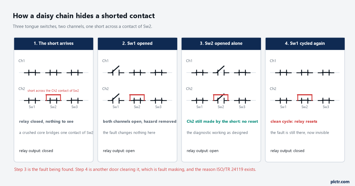
Step three is the diagnostic working. Step four is another door undoing it, which is the whole of the fault-masking problem in one picture.
What the relay expects on its two channels
The relay has opinions about how those channels behave, and they are not the ones people assume.
Simultaneity is the first surprise. GSR relays — the CI, DI, DIS, EM, EMD and SI family — have infinite simultaneity, which the manual states outright: one channel can close at T1 and the other much later at T2 in either order, and the input circuit is satisfied. There is no discrepancy timer to set and no 500 ms window to tune, so a sticking contact block that lets one channel lag by half a second will be accepted here and rejected by a Guard I/O module doing the same job. What the relay will not accept is one channel cycling several times before the other closes; the input stays red, the PWR/Fault indicator does not flash a pattern, and the only way out is to open both channels and close them again. That combination — an input that will not go green with no fault code to chase — sends more people to the spare relay than any other single behaviour on these units.
Green never comes back, and the fault indicator stays silent about the reason why.
Speed is the second. Recovery time, measured from the inputs turning off to the moment they can turn back on, is specified at 30 ms and measured as low as 20 ms. Input cycles shorter than 7 ms are ignored outright, cycles between 7 and 30 ms turn the output off even with automatic reset selected, and cycles longer than 30 ms are processed normally. A relay contact that bounces for 12 ms on a heavy door is inside the middle band, and the outputs drop for reasons that look like nothing at all on a meter.
And the reset is a press and a release, not a level. On the monitored manual setting the button has to be held between 0.25 and 3 seconds and the output closes on the release, with the mirror contacts of both contactors in the same loop so that a welded output keeps the relay from resetting at the next attempt. A tapped button does nothing. A jumpered reset terminal does nothing useful and quietly removes the contactor monitoring at the same time.
Tap the button and nothing happens, because the relay is timing the release.
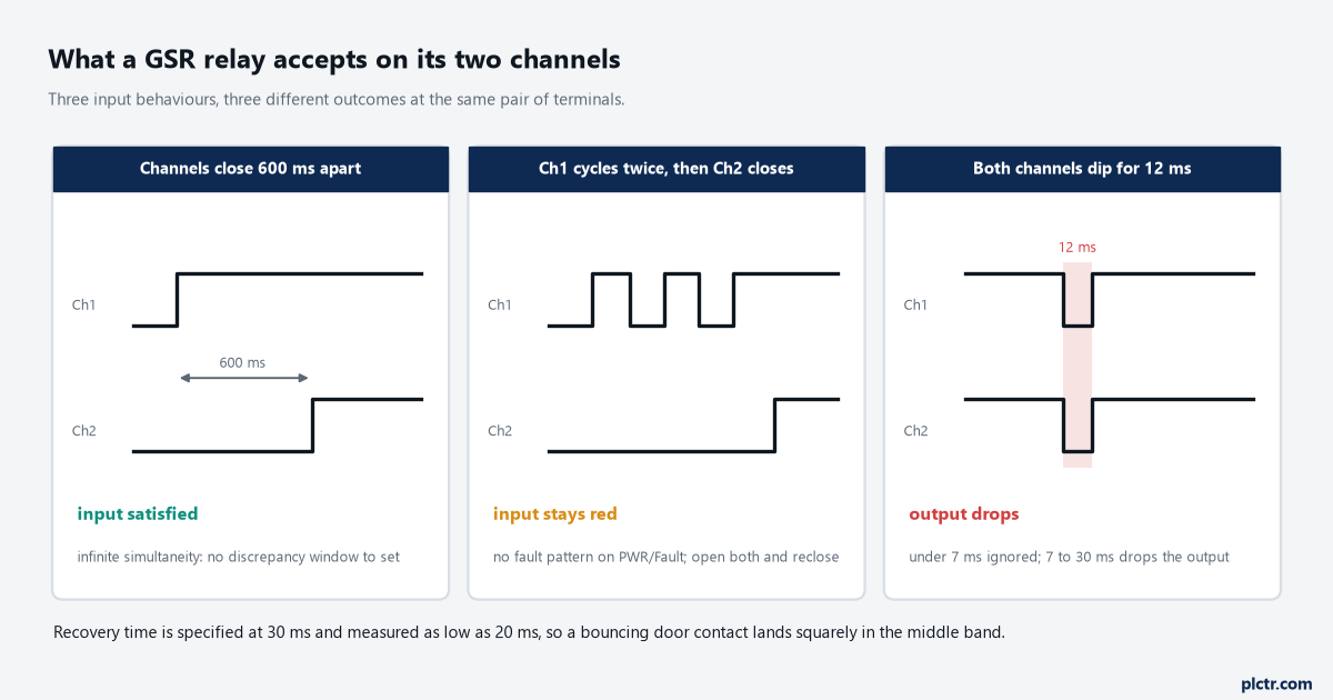
Same two wires, three outcomes. Only the middle case looks like a broken relay, and it is the one that is working as specified.
The thing everyone changes first
The switch. A coded non-contact device goes on the worst door, the file gets recalculated, and the number does not move, because the device was never the constraint — the chain was. The second attempt is usually a second relay so that two doors share each input pair of a DI relay instead of four sharing one, which does help, and helps in a way that can be written down: fewer devices per chain, less masking, more diagnostic coverage. The arrangement that ends the argument is one input pair per door, which on a DI relay means two doors per relay, and on a Guard I/O module means as many as you have input pairs and test sources for.
The chain is the constraint here, not the device hanging on the worst door.
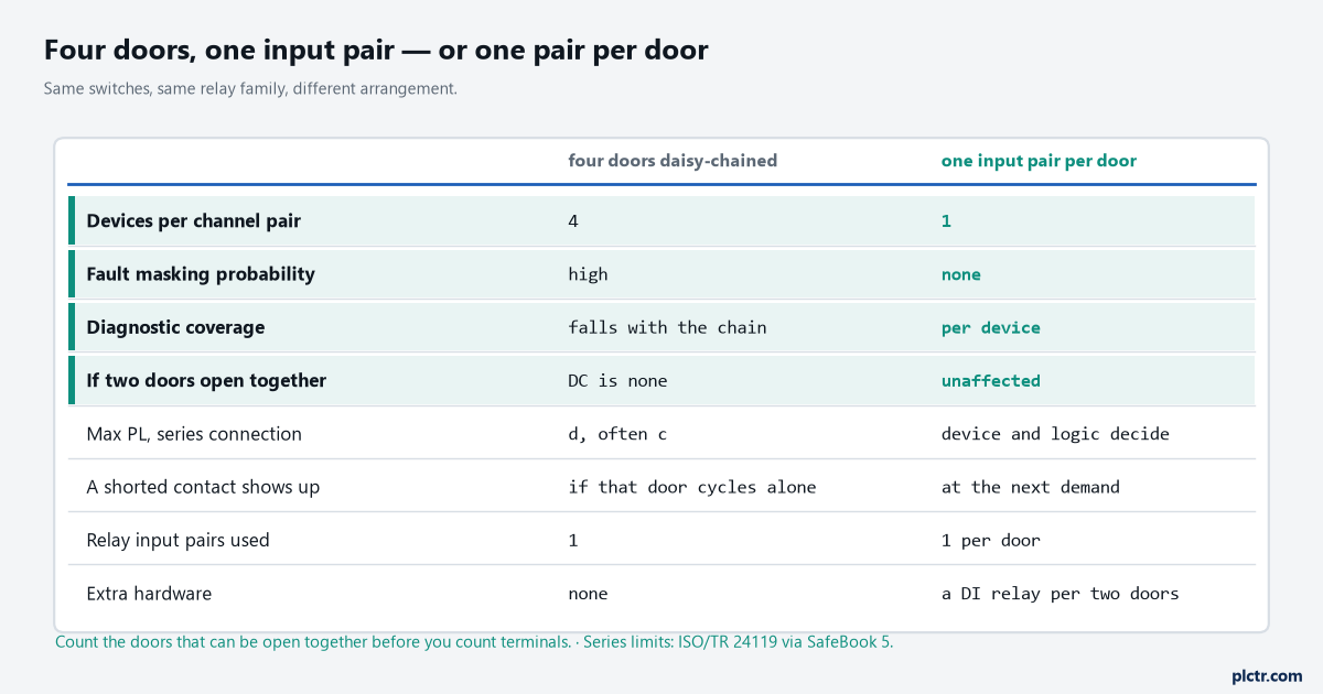
The right-hand column costs one relay per two doors. The left-hand column costs a level, and only shows it up when somebody recalculates.
Count the doors before you count the terminals.
What has to be true before PL d goes on the drawing
None of the above is a risk assessment, and none of it is validation.
The level comes out of a calculation over the whole function with the manufacturer’s data in it — B10d and your own cycle rate for the mechanical parts, PFHD for the electronic ones — plus a common cause failure score of at least 65 points, plus a diagnostic coverage figure you can justify for the arrangement you actually built rather than the one on the drawing. Then ISO 13849-2 asks for a documented verification and validation plan, which means testing that the function does what the specification says under fault conditions as well as normal ones: open each door individually, short each channel deliberately with the machine safe, and confirm the relay behaves the way the paragraphs above say it will. For the framing around that work — how a required level comes out of a risk assessment in the first place — the functional safety article covers the route from assessment to architecture, and the dual-channel E-stop on GuardLogix covers what the same input looks like when the logic is a safety controller rather than a relay. If the plant also works to the process standards, the IEC 61508 and 61511 rundown is the neighbouring family.
Next step: pull the functional safety data for the exact catalogue number on each door, count how many of those doors can be open together during a normal changeover, and if the answer is more than one, put the daisy chain on the list to break before you recalculate anything.