When the 1734-IB8S Will Not Run: Reading the Diagnostics First
MS flashing green on a 1734-IB8S means the device is in the Idle or Standby state, and the recommended action printed next to it is to configure the module and establish a connection. Nothing about the module is broken. It has powered up, passed its own diagnostics and is waiting for an owner that has not claimed it, which is a completely different job from the one you start if you assume a safety input card that is not running has failed.
The module face answers that question before Logix Designer is even open.
Everything below is a 1734-IB8S on a 1734-AENT adapter, owned by a Compact GuardLogix, read against 1734-UM013S, July 2026. The indicators are commissioning and troubleshooting information only; the manual is explicit that no safety function may be derived from them.
Read the module in one order and stop at the first thing that is not green
PWR, then MS, then NS, then the point indicators.
That order exists because each one rules out the ones below it, and jumping straight to the point indicators is how you end up chasing a wiring fault on a module that has no field power. PWR off means no field power applied to the segment, which on a POINT I/O base is a question about the 1734-AENT or the expansion power supply rather than about this module at all; PWR yellow means field power is out of specification, and it wants measuring at the base rather than at the supply, because the drop along a loaded base is exactly what that indicator exists to catch. MS steady red is an unrecoverable fault and is the only state on the card that genuinely means cycle power and then replace it. MS flashing red covers two different things — a recoverable fault, and a module that is not configured — and the manual’s own advice is to reconfigure and then use the network status indicator to tell them apart. NS flashing red is the one worth pausing on: one or more I/O connections are in a timed-out state, which means the connection existed and stopped, and that is a very different fault from one that never formed.
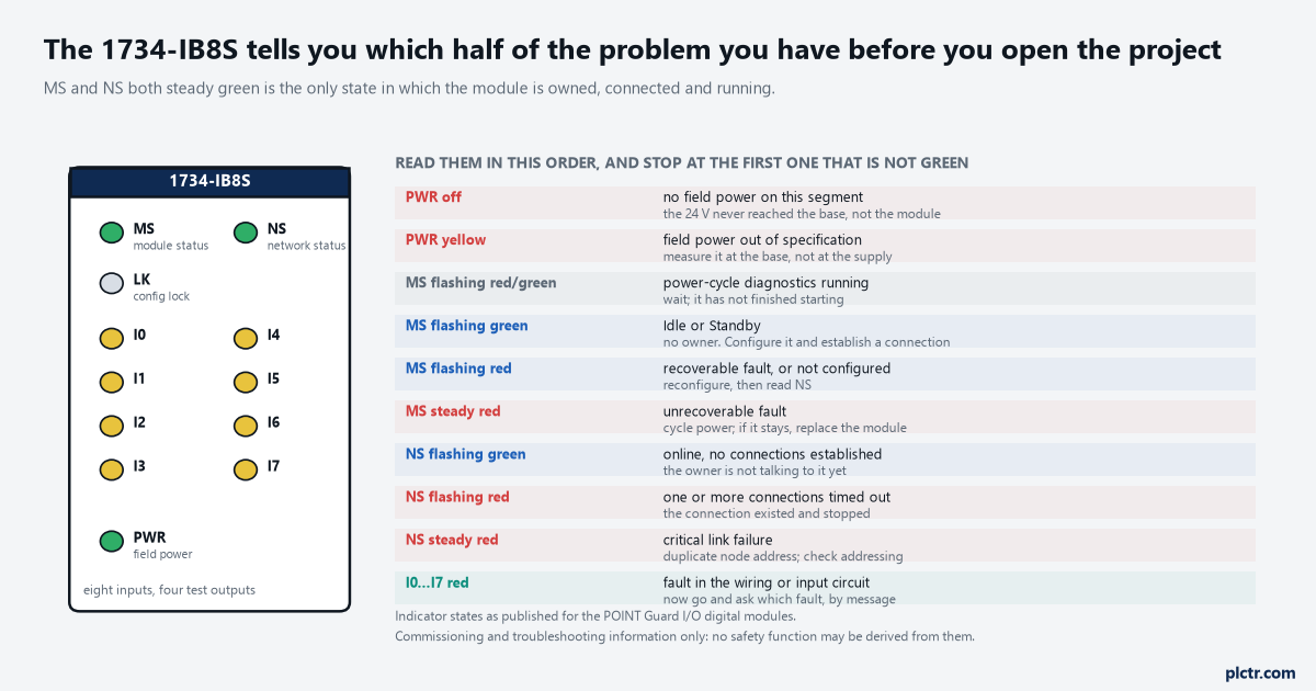
MS and NS both steady green is the only combination in which the module is owned, connected and running. Everything else names its own half of the problem.
NS steady red is a critical link failure, and the action printed against it is to check node addressing. Duplicate addresses on a POINT I/O backplane are rarer than they used to be and still happen after somebody replaces an adapter.
The module is fine and there is still no connection
A safety connection is six things agreeing, and a replacement module changes two of them.
The manual lists them plainly: the POINT Guard I/O module number, the POINT Guard I/O safety network number, the GuardLogix slot number, the GuardLogix safety network number, the path from the controller to the module, and the configuration signature. If any differences are detected the connection is lost and a yellow yield icon appears against the module in the project tree. Of those six, a module swap leaves four untouched — the slot, the two GuardLogix items and the path are all properties of the system rather than of the part you unclipped — and changes the two that matter most. A module out of the box carries no safety network number, or carries somebody else’s from a previous life, and until the replacement has been through the ownership reset the connection will not form no matter how correct the wiring is. Edit one configuration field afterwards and the configuration signature moves too, which is the second half of the same trap: the project now expects a signature the module has never been told about.
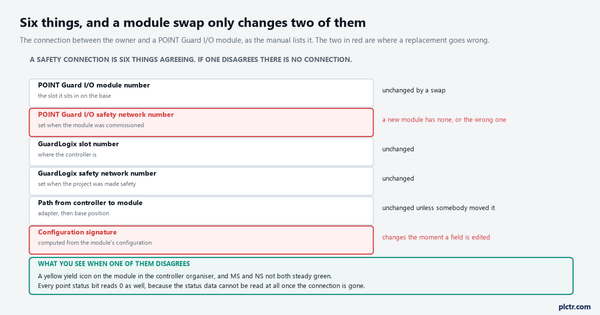
Four of the six survive a replacement untouched. The two in red are why a module that is electrically perfect still will not join.
There is a second way to lose a working connection and it is self-inflicted. Updating a module with ControlFLASH stops a running safety I/O connection, so the I/O connections have to be inhibited before the update rather than after somebody notices the cell has dropped.
Asking the module why the point is red
A red input indicator means a fault in the external wiring or the input circuit. It does not say which, and you do not have to guess.
Every 1734-IB8S point keeps a reason for its own fault, and a CIP Generic message reads it: Get Attribute Single, service code 0x0E, class 0x3D, attribute 0x6E, with the instance set to the point number plus one — so point 2 is instance 3 and point 7 is instance 8. Six values come back. 01 is configuration invalid, 02 is an external test signal error, 03 is an internal input error, 04 is a discrepancy error, 05 is an error in the other dual channel input, and 00 means the fault has cleared since you asked. Those six split the work cleanly. 03 is the module’s own input circuit and is the one value on that list that justifies a replacement; 05 says nothing is wrong with this channel at all and sends you to its partner; 02 sends you to the wiring and the test output, which is where most of them end up.
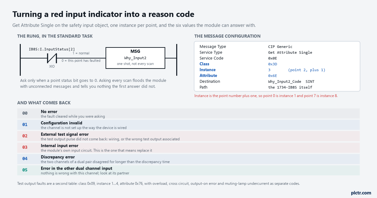
Instance is the point number plus one, which is the single most common way to configure this message wrongly and get a plausible answer about the wrong point.
Trigger it from the point status bit rather than from a timer. Individual point status reads 1 for normal and 0 for faulted, so a rung with XIO on InputStatus[2] driving a one-shot message asks exactly once, when there is something to ask about.
Combined status is an AND of all eight, so one faulted point pulls it low and it tells you nothing about which. And when the connection itself is gone every status bit in the controller data table reads 0, because the status data cannot be read at all.
The test pulse, and the fault code it produces
Reason code 02 has a specific, common, entirely fixable cause.
When a safety input is associated with a test output, the module does not check the level on the input; it checks that a notch it put on the 24 V comes back. The 1734-IB8S pulse is typically 525 µs wide in a 144 ms period, which is short enough that no contactor or relay downstream notices it and long enough for the module to read the reflection. Short the input line to 24 V and the notch disappears from the read-back while the input still looks healthily on, and that is the condition the external test signal error exists to catch. The trap is in the configuration rather than the field: the test source assigned to an input has to be the test output that is actually sourcing the 24 V for that input circuit, and the manual states the consequence of getting it wrong in one sentence — if the incorrect test source is entered, the result is pulse test failures on that input circuit. A pair of inputs wired from T0 but configured against T2 will fault every time, on a wiring loom that is perfectly correct.
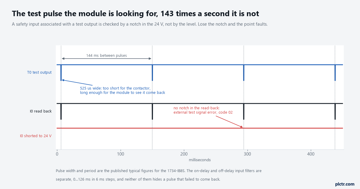
The module is looking for the gap, not for the voltage. A line held at a solid 24 V by a short reads as on and faults anyway.
Test outputs keep their own reason codes in a second object: class 0x09, instances 1 to 4, attribute 0x76, with overload, cross circuit, output-on error and muting lamp undercurrent as separate values. Muting is only available on T1 and T3.
The latch time you have to wait out
Clearing the cause does not clear the fault, and the delay is configured rather than fixed.
Safety input data stays off after an error until three things have happened in order: the cause is removed, the input is put back into its safe state, and the input error latch time elapses. Only then does the red indicator go out and the data become active again. That latch time is 0 to 65,530 ms in 10 ms increments with a default of 1000 ms, and it exists so that an intermittent fault lasting a few milliseconds is held long enough for the controller to read it. One second feels like a long time standing at a guard door pressing reset, and it is the reason a lot of “it did not clear” calls are really “we did not wait”. The same number is the reason a genuinely intermittent cross-circuit gets caught at all, so the answer is not to set it to zero.
Two other timings live on the same page and get blamed for the latch. The input delay filters, off-to-on and on-to-off, are 0 to 126 ms in 6 ms increments and default to 0; the discrepancy time for an equivalent dual-channel pair is 0 to 65,530 ms in 10 ms increments. None of the three does the other’s job.
Before you order a replacement
Work down the list in one pass: PWR, then MS and NS, then the yellow yield icon in the project tree, then a message to the point that is red. Four of those five checks take under a minute and only the last one needs a rung. If the answer comes back 03, internal input error, then the module has earned its replacement and you already know to reset the safety network number and re-download the configuration signature afterwards.
One thing to check on an older panel before you blame anything else: Series A POINT Guard modules want a 1734-CTM spacer between every module once the ambient goes above 40 °C, and a stack of them wedged together in a summer enclosure will misbehave in ways no reason code explains. Series B and C do not need the spacers up to 55 °C.
The reset and interlock logic that sits above all this is in the dual-channel E-stop article, the architecture decisions behind it are in functional safety from risk assessment to PL d, and the instructions that consume these input tags are covered in safety add-on instructions.