Scaling a 4-20 mA Temperature Transmitter on a CompactLogix 5380
Put Low Signal 4 mA, High Signal 20 mA, Low Engineering 0.0 and High Engineering 250.0 into a 5069-IF8 channel and Local:2:I.Ch00.Data arrives at the controller as a REAL already in degrees Celsius. There is no scaling rung, no raw count, and nothing for a CPT to do. The Compact 5000 analog modules return channel data in IEEE 32-bit floating point, so in Logix Designer the tag is a REAL and the integer arithmetic everybody learned on a 1769-IF4 has nothing to operate on.
What is worth your attention instead is the four things the channel will tell you about the transmitter, and none of them survive a clamp.
Everything below is a 5069-IF8 in the local bank of a 5069-L320ER, on 5069-UM005F, December 2024, with a two-wire Pt100 head transmitter ranged 0 to 250 °C.
The four fields, and the fifth that matters more
Scaling on this module is two points on the signal and two points in your units.
The Low Signal point equates to the Low Engineering point and the High Signal point to the High Engineering point, and the module interpolates between them; in the Studio 5000 dialog the option is listed as Percent of Full Scale, which is the name that confuses people into thinking it only does percentages. It does not. Leave Low Engineering at 4 and High Engineering at 20 and the tag reports milliamps; set them to 0.0 and 100.0 and it reports percent; set them to 0.0 and 250.0 and it reports the degrees your transmitter was ranged for. The choice costs nothing in resolution either way, because picking two points for your application does not narrow the range of the module, and the module range stays what it was regardless of how you scale it.
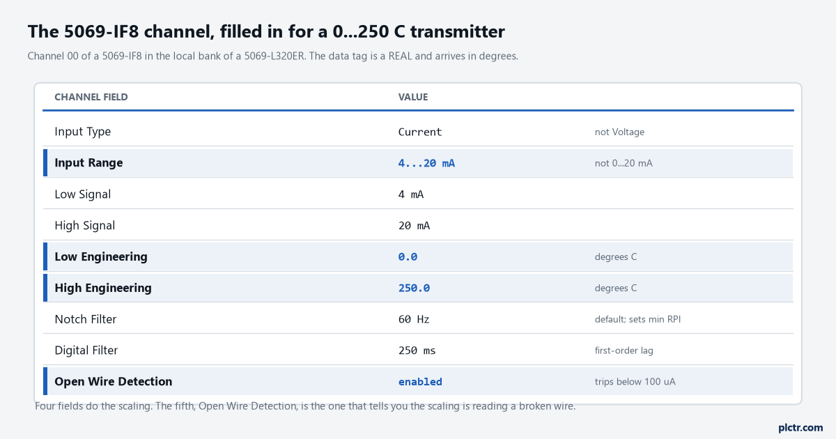
Four fields do the scaling. Open Wire Detection is the one that tells you whether the scaled number means anything.
Tick Open Wire Detection while you are on that page.
Pick 4…20 mA, not 0…20 mA
This is the decision that people get wrong for a reason that sounds sensible.
The Input Type dropdown offers Current or Voltage, and under Current the 5069-IF8 offers 0…20 mA and 4…20 mA as separate ranges. The argument for 0…20 mA is that it covers everything, so nothing can ever sit outside it, and somebody then scales 4 mA to 0 °C in logic and moves on. What that throws away is the entire diagnostic layer. On the 4…20 mA range the module has an underrange threshold at 3 mA and an overrange threshold at 23.00 mA, and it sets I.Chxx.Underrange or I.Chxx.Overrange when the loop crosses one. On 0…20 mA the underrange threshold drops to -0.07 mA, which a broken transmitter will never reach, so a loop that has fallen to 2 mA reads as a slightly negative temperature and nothing in the controller objects. The two ranges have identical resolution. One of them knows when the transmitter is failing.
Both thresholds have a 0.07 mA deadband, so an underrange that trips at 3.00 mA does not clear again until the loop comes back up to 3.07 mA. That is deliberate: a transmitter drifting around the threshold would otherwise chatter the bit at whatever your RPI is.
And underrange is not an alarm, in the module’s own vocabulary. Ticking Disable All Alarms does not switch it off; only disabling the channel does that.
What the channel does below 4 mA, and why you should let it
The module does not clamp at the endpoints you configured, and that is the feature.
With 0.0 and 250.0 in the engineering fields, a loop that has sagged to 3 mA reports a negative temperature rather than pinning at zero, and the published Percent of Full Scale table says the same thing in percent: 3.0 mA comes back as -6.00% on a standard module, 23.0 mA as 118.75%, with 12.0 mA sitting exactly on 50.0% where you would expect it. A reading of minus fifteen degrees on a vessel that cannot physically go below ambient is an unmistakable signal that the loop is broken, and it is a signal you only get if nothing downstream has clamped it first. The habit worth breaking is the LIM instruction that limits the value to 0.0 and 250.0 before the HMI sees it, because that turns a failing transmitter into a perfectly believable cold vessel and the operator has no reason to question it.
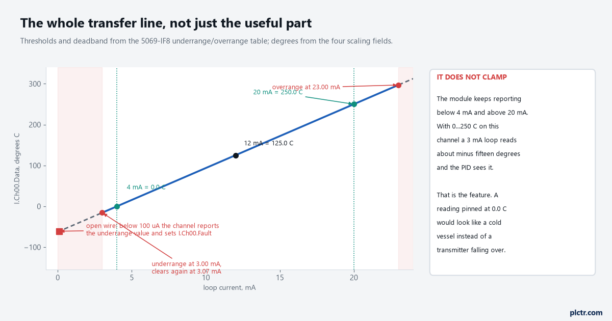
The useful part of the line is between 4 and 20 mA. The parts either side are the diagnostics, and clamping them away is what turns a broken loop into a plausible reading.
Below 100 µA in current mode the module calls it an open wire, sets I.Chxx.OpenWire, sets I.Chxx.Fault, and drives the channel data to the scaled value that corresponds to the underrange. A cut cable and a dead transmitter look different at that point, which is more than most analogue cards will do for you.
So the rung you write is not a scaling rung. It is a validity rung.
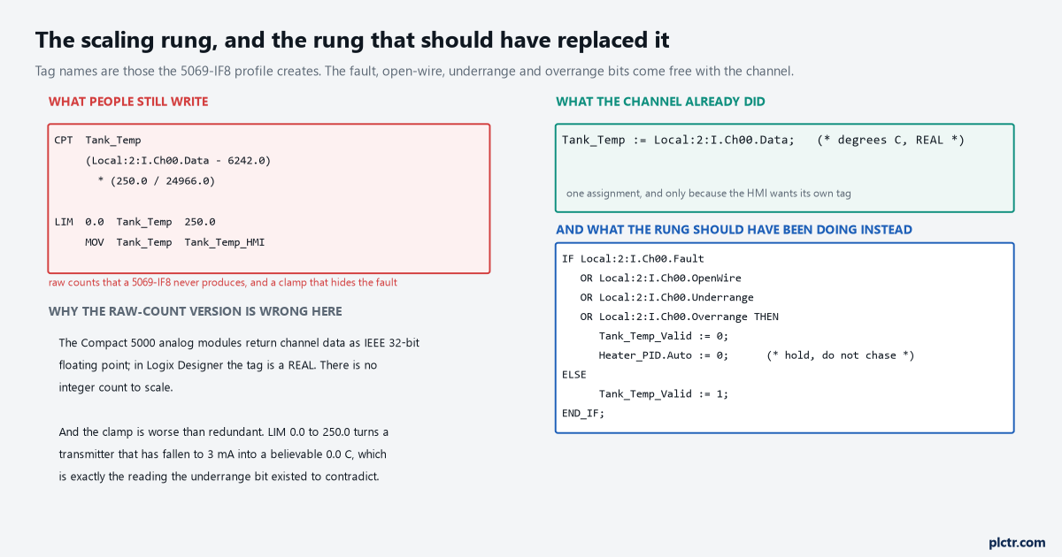
The four bits on the right already exist in the channel’s input tag. Reading them is the work the scaling rung was doing instead of.
The notch filter decides your RPI, not the other way round
Nobody sets this field on purpose, and it quietly sets the RPI you are allowed to ask for.
The notch filter is part of the analogue-to-digital converter and it attenuates at the frequency you pick, so 60 Hz removes 60 Hz mains noise and its overtones, and the default on a 5069-IF8 is 60 Hz. The cost is sample time. With all eight channels enabled at the same setting, 60 Hz wants a minimum module RPI of 80 ms for faster sampling or 240 ms for better noise rejection; drop to 5 Hz because a thermocouple article said slow is good and the recommended minimum jumps to 750 ms, with a published note that four or more channels at 5 Hz cannot be refreshed every RPI at all and instead deliver fresh data about every other one. Go the other way to 1000 Hz and the minimum falls to 8 ms, but you have given up the mains rejection that made the reading steady. The channels are also grouped, 00 to 03 and 04 to 07, and enabling any channel in the other group adds 0.2 ms to the recommended minimum for every enabled channel in each group.
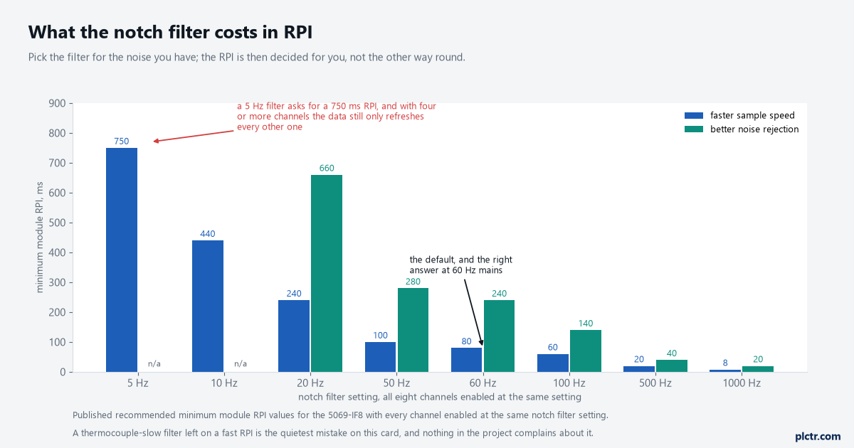
Pick the filter for the noise in the panel, then take the RPI it hands you. A 5 Hz filter on a 20 ms RPI is asking the module for data it has not finished collecting.
For a vessel temperature none of this is tight. Leave the notch filter at 60 Hz, set the RPI to something sane for an EtherNet/IP connection budget, and use the separate Digital Filter field for smoothing instead. That one is a first-order lag in milliseconds, where the input reaches 63% of a step change after one time constant, and 0 disables it. A 250 ms value takes the twitch out of a thermowell reading without touching the sample rate.
The alarms are in your units, and they latch
Process alarms on the channel trigger in whatever units you scaled to.
That is the part worth knowing before you put the high limit in a rung: the Process Alarm trigger points are related to the scaling parameters, so with 0.0 and 250.0 configured the High limit is typed as 180.0 and not as 14.72 mA or as a percentage. There are four of them, High high, High, Low and Low low, they are disabled when the module tags are created, and each one can latch. Latching is where people get caught, because unlatching is not a level. You toggle O.Chxx.HAlarmUnlatch from 0 to 1 and then you must set it back to 0, and if you leave it at 1 the next occurrence of that alarm stays latched despite the tag being high. A rate alarm sits alongside them, in engineering units per second, and it behaves the same way.
The alarm deadband works on the same principle as the range thresholds: the status bit stays set while the input remains inside the deadband, so a value hovering on the limit does not flutter.
Before you leave the panel
Read I.Ch00.Data with the loop at 4 mA, at 12 mA and at 20 mA from a loop calibrator, and confirm 0.0, 125.0 and 250.0 on the tag. Then pull one leg of the transmitter and watch I.Ch00.OpenWire and I.Ch00.Fault both go to 1 while the data drops to the underrange value; that test takes twenty seconds and it is the only proof the diagnostics are actually enabled.
If the channel is feeding a loop, the validity bits belong in front of it rather than behind it, so the controller holds the last good output instead of chasing a broken transmitter into a limit. Setting up and tuning the PID loop is the next job, and the analogue alarm instruction is where the alarming belongs once there is more than one channel to look after. For the wiring side of a Compact 5000 bank, start with the I/O module basics.