K1 is a 110 V AC contactor on a saw, its coil is switched by a solid-state relay, the SSR is driven from output pair 0 of a 1791ES-IB8XOBV4, and every 600 ms the contactor makes a small tick you can hear from the door of the panel. The scope on O0+ shows why: the output goes low for 700 µs, 1.67 times a second, for as long as it is on. That is not a fault. Those are the module’s safety output test pulses, printed in the Guard I/O user manual as 700 µs wide every 600 ms, and it is there to prove that the output can still switch off. The tick is what happens when something between the safety output and the coil is fast enough to notice the gap. A contactor coil on the pair directly is not. Everything below is that machine – a GuardLogix 5580 with the 1791ES module and 100S-C09 contactors – plus the numbers from the POINT Guard I/O manual for the 1734-OB8S, and what the same test looks like on a Siemens F-DQ.
Short answer: there is no filter setting on the module. The only filter you control is the response time of the thing you connect.
What the 700 µs pulse is checking
While a safety output is on, the module pulls it low for 700 µs and reads it back. If the terminal is still at 24 V during that gap the output has been shorted to a supply, and the manual lists three things the test catches: a short from a sourcing output to the positive supply, a short from a sinking output to the negative side, and a short between two output lines of the same polarity. Find one and the output data and the individual output status go off, and stay off for at least the Output Error Latch Time, 1000 ms by default, so the controller is sure to see it. The 1734-OB8S and OBV2S do the same job with a 475 µs pulse every 575 ms, and both manuals carry the same one-line warning underneath the figure: to prevent the test pulse from causing the connected device to malfunction, pay careful attention to the input response time of the device. That sentence is the whole article. The pulse is short on purpose, short enough that a coil – any coil, contactor or interposing relay – cannot drop out in it, because a coil’s release time is tens of milliseconds and it stores energy. A semiconductor input stores nothing. An SSR with a 0.1 ms input follows the gap exactly, its zero-cross output waits for the next zero crossing before it re-arms, and at 50 Hz that is up to 10 ms with no voltage on the AC coil. The AC coil does not drop either, but its flux collapses for half a cycle and the armature moves. That is the tick.
Input-side pulses are the same idea, 500 µs every 150 ms from a 1791ES test output, and the same warning applies.
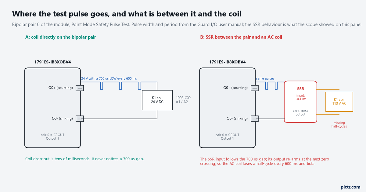
Same output, same pulse. On the left the coil is the filter and nothing happens. On the right the SSR input is faster than the pulse, and the AC coil behind it loses a half-cycle every 600 ms.
The scope capture that settles it
Three traces, one afternoon, and the argument about a faulty module was over.
The top trace is O0+ against 0 V: 24.1 V with a 700 µs drop to under a volt, every 600 ms, exactly as the manual draws it. The middle trace is the SSR output into the 110 V coil, zoomed to 100 ms around one pulse: the sine wave stops at 250 ms and does not come back until the next zero crossing, one half-cycle gone, and the tick on the audio recording lines up with it to the millisecond. The bottom trace is what the same pulse does to a 24 V DC 100S-C09 coil wired straight across the bipolar pair on the second machine: the coil current sags by about 10 mA for a few milliseconds and recovers, and the contactor’s mirror contact never moves, which the module’s own feedback input confirms because the CROUT never saw a feedback change. Measure it once on your own panel. A scope on the output terminal and a clamp on the coil lead is fifteen minutes, and it tells you whether your load is in the left column or the right one without anyone guessing.
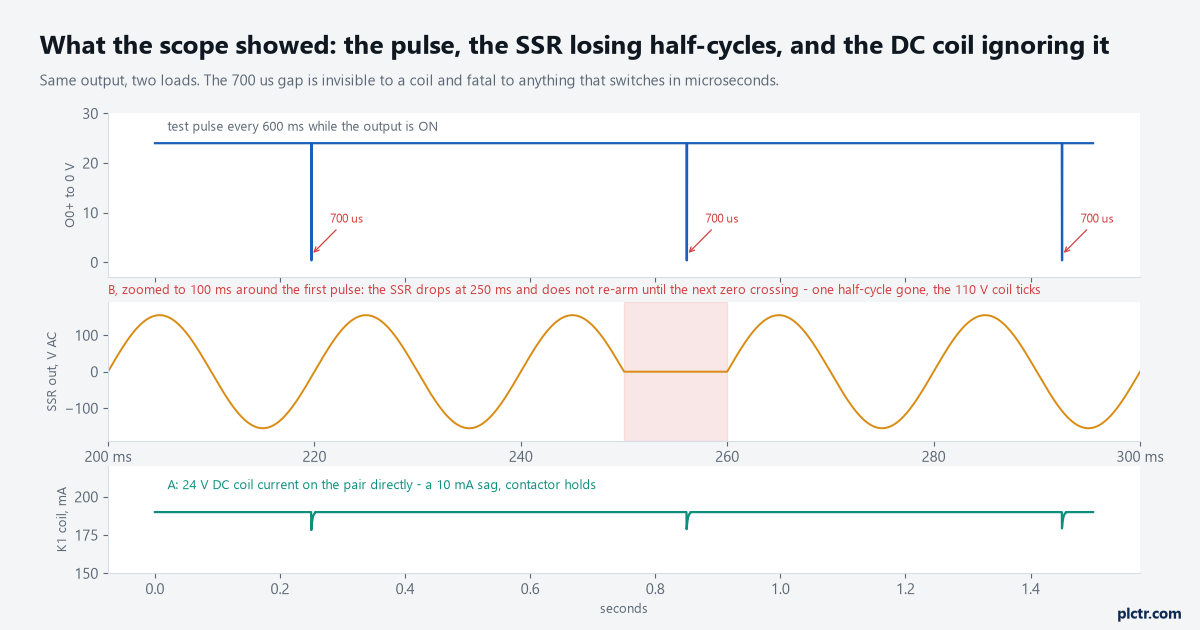
The pulse is the same in both builds. The SSR turns it into a missing half-cycle on an AC coil; the DC coil turns it into a 10 mA ripple nobody would notice.
The capacitor that makes it worse
The first suggestion on that call, before anyone had a scope on it, was a capacitor across the SSR input to ride through the gap.
It is the wrong fix, and the manual tells you why in the sentence that describes the test: the pulse test detects if 24 V remains on the output terminal during the LO pulse due to a short to 24 V. A capacitor big enough to hold the SSR input up for 700 µs holds the output terminal up for 700 µs as well, and to the readback that is indistinguishable from a short to the supply. The output faults, the pair goes off, the status LED goes solid red, and now you have a contactor that will not pull in at all instead of one that ticks. Smaller capacitors do less of both. The same reasoning covers an RC snubber on the terminal, a long unshielded run with a lot of capacitance to a parallel 24 V wire, and the “just put a diode and a cap on it” advice that works fine on a standard output card. Nothing that stores charge belongs on the terminal side of a pulse-tested output. Put the energy storage where it belongs, in a coil.
If the output faults the moment you add a component, the component is the fault.
What actually fixes it
Two fixes are real, and one is a decision rather than a fix.
The first is to take the SSR out and drive the contactor coil from the safety output directly, which on that machine meant a 24 V DC coil in place of the 110 V AC one – a 100S-C09 with a DC coil across O0+ and O0-, the bipolar pair switching both sides so a short on either wire is seen. That also gives the CROUT a mirror contact to read, which the SSR never could; EDM and the mirror contact is the wiring for that. The second, where the AC coil has to stay, is an interposing relay with a coil on the pair and mechanically linked contacts switching the AC coil. Its coil ignores the pulse and its NC contact goes back to a feedback input, so the interposing relay is monitored instead of being an unmonitored semiconductor in the stop path. The decision is Point Mode. The output configuration in the Guard I/O manual offers Safety, which enables the point and does not pulse test it, and Safety Pulse Test, which does; set Safety and the tick stops immediately, and so does detection of a short to 24 V and of an output shorted to its neighbour. That is a change to the diagnostic coverage of the output, the DC in ISO 13849-1 terms, and it belongs on the validation record with a reason next to it, not in a commissioning note that says “turned off pulse test, chatter gone”.
The manual’s own case for Safety without pulse test is a device that pulse-tests itself, the way a light curtain does on the input side.
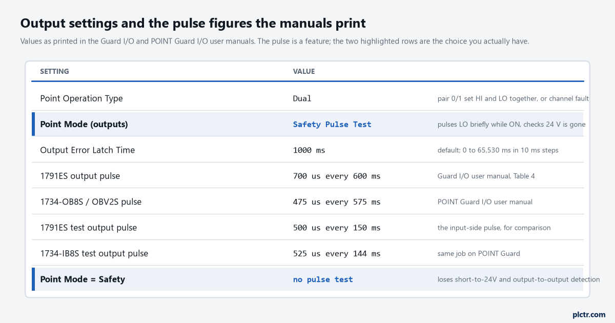
The two highlighted rows are the only choice the module gives you. Everything else about the pulse is fixed.
Loads that notice safety output test pulses, loads that do not
Here is the list from the three calls that produced this article, and what each needed.
A 24 V DC contactor coil across the pair: nothing, a 10 mA sag. An interposing relay coil: nothing, and read its NC contact back. An SSR into an AC coil: a coil in place of the semiconductor. A standard input reading O0+ so the HMI can show “contactor on”: it toggles every 600 ms and a counter on that bit runs at 100 an hour, so use the module’s own output status tag instead of a wire – O.Pt00OutputStatus is already in the controller and it does not pulse. A drive STO input or a robot controller’s safety input: depends entirely on what that device specifies for test pulse tolerance, and most of them print a number, so read it before you wire it rather than after. A capacitor: take it off. A device that pulse-tests its own input: two pulse trains on one wire, and the manual’s Point Mode Safety exists for exactly that device.
Nobody has ever fixed this with a setting on the module, because there is not one.
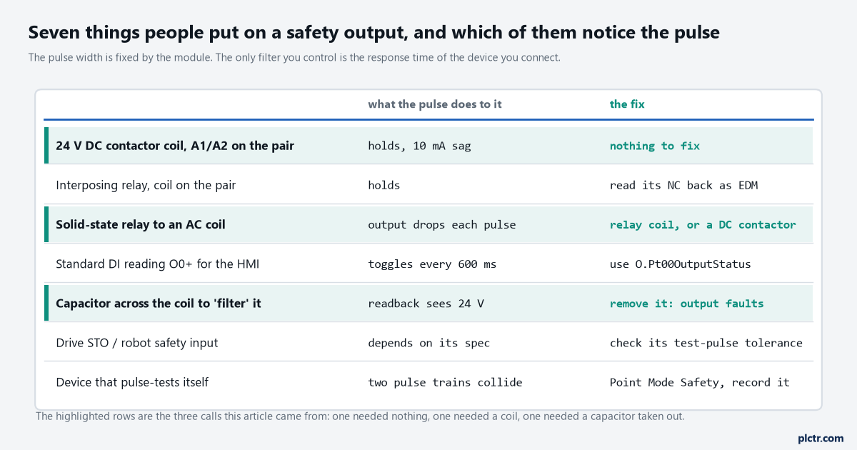
The rows are the calls, in the order they came. Three of the seven needed a change; none of them needed a module.
The Siemens side, briefly
An ET 200SP F-DQ tests its outputs the same way, by switching them off for a short time and reading back, and the SIMATIC Safety manual has a note that follows from it: for F-I/O with outputs, acknowledgement after a channel fault may only be possible some minutes after the fault is eliminated, because the module has to apply its next test signal before it can tell the fault is gone. So an F-DQ output that faulted on a short and then refuses to reintegrate for a while after the wire is fixed is not stuck; it is waiting to test. The pulse widths and periods of the F-DQ 4x24VDC/2A PM HF live in that module’s equipment manual, which I could not open this time, so measure them on the terminal rather than take a number from me. The load rules are identical: coils fine, semiconductors check the spec, capacitors off. And the FDBACK block that reads a contactor’s mirror contact has a QBAD_FIO input for the passivation status of the F-DQ channel driving the coil, so a passivated output is not reported as a feedback fault on top of everything else; what passivation is and how the channel comes back is a separate article, the one on reintegration after a channel fault, which follows this one.
Next step
Put the scope on the output terminal and a clamp on the coil lead, and run the machine for a minute. If the terminal shows the 700 µs dip and the coil current shows a sag and nothing else, the output is healthy and the tick is coming from a semiconductor somewhere between them; find it. If the output LED is solid red instead, read the contactor feedback article before you swap anything, because a readback fault and a feedback fault look alike from the HMI and are cleared differently. The input-side version of the same pulse – and what a short between two channel wires looks like to it – is the cross-fault detection article that follows this one. And if the question is whether this machine needs a safety PLC output at all or a 440R relay with a plain contact, that is the relay-or-controller article.
The coil is the filter. Everything faster than a coil needs its own spec sheet read first.