A station where the carrier stops in front of the head wants HF at 13.56 MHz and a read window of 10 to 200 mm; specify UHF there for the extra range and you will spend a week filtering stray reads from the aisle behind. That part of RFID PLC integration is decided in the mechanical design, before anyone opens Studio 5000. What comes after it is the trigger, busy, done and error handshake, which has to survive a carrier moving through the field faster than the reader can answer. Here is how the physics and the logic fit together on a Logix system.
The system in this example
| Item | Detail |
|---|---|
| Controller | 1756-L83E, Studio 5000 v33 |
| Reader | Turck TBEN-S2-2RFID-4DXP, two channels, EtherNet/IP |
| Read head | Turck Q80 HF, 13.56 MHz, ISO 15693 |
| Tag | HF disc tag on a pallet carrier, 2 kbyte user memory |
| Second station | SICK RFU620 UHF for the pallet gate, 865 to 868 MHz |
| Alternative | Balluff BIS V processor, same handshake, different byte map |
Pick the frequency before the mechanics are built
| HF, 13.56 MHz | UHF, 865 to 928 MHz | |
|---|---|---|
| Typical range | 10 to 200 mm | 0.5 to 6 m |
| Metal tolerance | Good with the right head and a metal-mount tag | Poor, reflections everywhere |
| Orientation | Forgiving at short range | Matters a lot |
| Reading a moving part | Fine at conveyor speed with a large head | Fine, but you will read the next lane too |
| Good for | Pallet carriers, tool holders, fixtures, work in progress | Dock doors, gates, pallet counting |
The mistake I see most often is UHF chosen for a station where a part stops in front of a head. The extra range buys nothing and the stray reads from the aisle behind cost you a week of filtering. If the part stops, use HF.
Get the reader onto the network
On EtherNet/IP, install the vendor EDS file first, then add the device. An AOP gives you named tags and saves an hour of counting bytes. A generic device connection works too:
- Right-click the Ethernet port in the I/O tree, choose New Module, then Generic Ethernet Module if no profile is installed.
- Set Comm Format to Data – INT or Data – SINT according to the manual. SINT is easier when the map is byte oriented.
- Enter the assembly instances and sizes exactly as the manual gives them. Input assembly 101 with 32 bytes and output assembly 102 with 32 bytes is a typical HF gateway.
- Set the RPI to 20 ms. Faster does not read tags faster, the reader is the bottleneck.
- If the module faults with 16#0109 after the download, the connection size is wrong by a byte or two. Count again, and check whether the manual gives the size in bytes or in words.
The EDS install is in EDS file installation via RSLinx. The wider network setup, including how the reader sits behind a managed switch with the rest of the cell, is in using EtherNet/IP in PLC communication.
On serial readers the picture changes only at the transport layer. An RS485 reader speaking Modbus RTU needs a gateway or a serial module, and you exchange the same command and status registers by polling instead of by cyclic connection. The register numbers come from the reader manual. The comparison of what each protocol costs you is in communication protocols for PLC and SCADA systems.
Map the raw bytes into a UDT on the first day
The input assembly arrives as an array of SINT. Leave it that way in the logic and you will be reading Reader:I.Data[14]
(* UDT: RFID_Station                                     *)
(*   Cmd_Code      INT   1 = read, 2 = write, 3 = reset  *)
(*   Start_Addr    INT   byte offset in tag memory       *)
(*   Length        INT   bytes to move                   *)
(*   Trigger       BOOL  rising edge starts the cycle    *)
(*   Busy          BOOL  from the reader                 *)
(*   Done          BOOL  from the reader                 *)
(*   Error         BOOL  from the reader                 *)
(*   Error_Code    INT   vendor code, log it             *)
(*   UID           SINT[8]   tag serial number           *)
(*   Payload       SINT[32]  user data                   *)

(* Structured Text, one station, 5 second watchdog *)
CASE Stn1.State OF
  0:  (* idle, wait for a carrier in position *)
      IF Carrier_In_Position AND NOT Stn1.Done THEN
          Stn1.Cmd_Code   := 1;
          Stn1.Start_Addr := 0;
          Stn1.Length     := 32;
          Stn1.Trigger    := 1;
          TON_Read.PRE    := 5000;
          Stn1.State      := 10;
      END_IF;

  10: (* wait for the reader *)
      TON_Read.TimerEnable := 1;
      TON_Read();
      IF Stn1.Done THEN
          COP(Reader_In.Data[4], Stn1.UID[0], 8);
          COP(Reader_In.Data[12], Stn1.Payload[0], 32);
          Stn1.Trigger := 0;
          Stn1.State   := 20;
      ELSIF Stn1.Error OR TON_Read.DN THEN
          Stn1.Trigger := 0;
          Read_Fault   := 1;
          Stn1.State   := 90;
      END_IF;

  20: (* data is good, hand it to the tracking logic *)
      TON_Read.TimerEnable := 0;
      Carrier_ID_Valid := 1;
      Stn1.State := 0;

  90: (* fault, operator has to clear *)
      TON_Read.TimerEnable := 0;
      IF HMI_Reset THEN
          Read_Fault := 0;
          Stn1.State := 0;
      END_IF;
END_CASE;
The watchdog is not optional. A reader that never answers because the head cable came loose will otherwise leave the station waiting forever, and the operator will report it as a conveyor problem. If UDTs are new to you, the basics are in user defined datatype UDT usage examples.
Run the handshake the way the reader expects
Every RFID gateway I have worked with uses some version of the same four signals. You raise a trigger with the command loaded, the reader raises busy, then raises done or error, and you drop the trigger to acknowledge. The reader drops done when it sees the trigger go away.
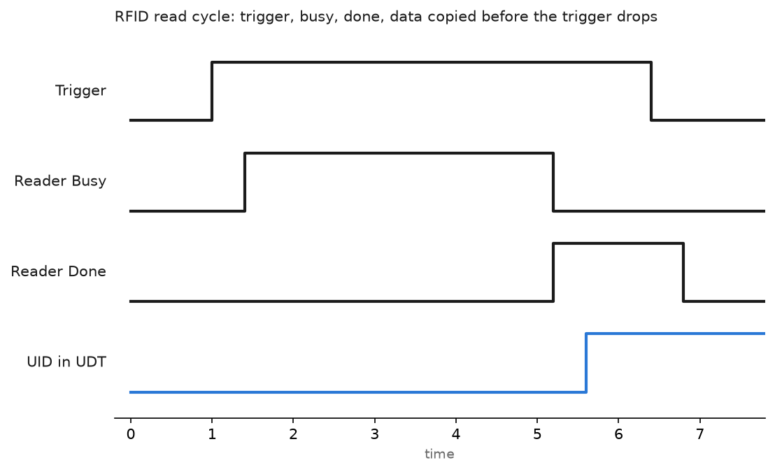
Three details decide whether this is reliable.
Copy the data before you clear the trigger. Some gateways keep the data buffer valid only while done is high. Clear the trigger first and you get a UID of all zeros in one cycle out of fifty.
Never trigger on a level. A trigger held high while the carrier leaves gives you a read of whatever arrives next. Edge trigger it from a position sensor.
Log the error code, not just the error bit. Vendor codes distinguish no tag in field from checksum failure from write protected, and those three have completely different causes.
Prove the installation before you write the sequence
Half a day with the vendor tool and a tape measure saves a week of arguing about the network.
- Mount the head, then find the real read window. Move a tag through the field by hand and mark where the reader LED comes on and goes off. Write the distance on the drawing.
- Check the window against the fastest line speed. A 90 mm window at 0.6 m per second gives you 150 ms of contact. If the read takes 120 ms you have almost no margin.
- Read the same tag two hundred times from the vendor software and count failures. One failure in two hundred on the bench becomes several per shift on the line.
- Repeat with the carrier in its worst position, which usually means pushed to one side of the guides and sitting against the steel.
- Record the antenna power, the tag type and the head to tag distance in the panel folder. The next person to replace a head needs all three.
Field notes
The 98 percent line. A carrier system read 49 out of 50 pallets. The missing one was always the same pallet. The tag had been mounted 4 mm closer to the steel frame than the rest, enough to detune an HF tag that was not a metal-mount type. Replacing one tag fixed a fault that three people had blamed on the network.
Byte order on the UID. The reader sent the eight byte UID most significant byte first. Logix copied it straight into a SINT array, the HMI showed it reversed, and the MES rejected every carrier. A SWPB on each pair fixed it, but only after somebody printed the raw bytes and compared them with the label on the tag.
Two heads too close together. Two HF heads 200 mm apart on the same conveyor rail interfered whenever both were energised. Symptom was random read failures on both, worse when the line ran fast. The vendor minimum separation for that head was 500 mm. We moved one head 300 mm downstream and added a small offset to the position sensor.
UHF reading the aisle. A gate reader at 30 dBm counted pallets in the adjacent lane. Dropping the power to 21 dBm and adding a simple filter on read count per second cleaned it up. Power is not free range, it is free false reads.
Frequently asked questions
How much data should I keep on the tag?
As little as possible. A serial number and a small status word is usually enough, with the real record in the database. Every extra byte is read time, and read time is what you lose when the line speeds up.
How fast can I read a moving part?
It depends on the head size and the data length. A UID read from an HF tag in a 100 mm field is typically tens of milliseconds. A 200 byte read is not. Test it at line speed with the actual tag before you design the sequence around it.
Can I write to a tag while the carrier moves?
You can, and you should not. A failed write leaves a half written block that no reader can interpret. Write at a station where the part is stationary and verify by reading it back.
What if two tags are in the field?
HF heads usually return an error or the first tag found. UHF readers return a list. Decide which behaviour you need before you pick the reader, because the logic differs completely.
Do I need the vendor configuration software?
For a first setup, yes. Antenna power, tag type and the byte map are set in the reader tool, and guessing those from the PLC side wastes a day.
Next step
The reader is one device on a cell network that also carries drives and I/O. Getting that traffic to behave is the subject of using EtherNet/IP in PLC communication, and if the reader is not showing up in the module list at all, start with EDS file installation via RSLinx.