JMP, LBL and MCR on a ControlLogix: Skipping Rungs, and Why MCR Is Not a Stop
Rung 14 of a filling machine carries OTL Glue_Pot_On and it sits between two MCR instructions. Open the guard, the zone goes false, every OTE inside it clears to 0 — and the glue pot stays hot, because a false rung leaves an OTL exactly where it was. The controller did nothing wrong. The 1756-RM018A-EN-P execution table on page 85 says an OTL does not change its data bit when rung-condition-in goes false, and an MCR zone works by making rung-condition-in false for everything inside it.
So: MCR disables a block of rungs inside one program, JMP and LBL skip a block of rungs inside one routine, and neither of them removes power from anything. If you want the scan time back, use JMP. If you want a section of logic to behave as though it were not there, use MCR and read the rest of this page first.
Everything below is a 1756-L83E on v34, Studio 5000 Logix Designer, ladder only — none of these three instructions exists in function block or structured text.
What the two MCR rungs actually do
The name is borrowed from a relay panel and that is most of the confusion.
An MCR instruction has no operands. It must be the last instruction on its rung, and it works by toggling a single override bit each time it executes with rung-condition-in false. That is why you need two of them: the first, conditioned on whatever decides the zone, and a second, unconditional, to toggle the bit back. While the override bit is set, every instruction between the two MCR rungs executes as though its rung were false — so an OTE clears, a TON has its accumulator cleared, a MOV does not write, and the rungs cost less scan time than they would have done, because a false execution is generally quicker than a true one. There is exactly one override bit per program. You cannot nest zones: put an MCR pair inside another MCR pair and what you get is not a nested zone but several smaller ones, each toggling the same bit, which is the sort of thing that works on the bench and produces a machine nobody can explain three months later.
The bit resets on its own at the end of the routine. Write the closing MCR anyway — online edits move rungs around, and a zone with no visible end is a zone somebody will extend by accident.
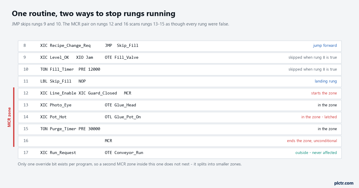
Two different mechanisms in one routine. The JMP pair skips rungs outright; the MCR pair scans them with every rung forced false, which is not the same thing at all.
Why an MCR zone is not a stop
This is the part that has consequences, so it goes here rather than at the bottom.
The manual says it in plain words on page 686: the MCR instruction is not a substitute for a hard-wired master control relay that provides emergency-stop capability, and you should still install one to provide emergency I/O power shutdown. That warning exists because the instruction looks exactly like a stop and behaves nothing like one. Dropping the zone changes bits in the controller’s data table. It does not open a contact, it does not de-energise the output module, and 24 V is still sitting on every output terminal waiting for the next rung that writes to it. A latched output stays latched, because an OTL that goes false does not clear. An OTU inside the zone stays false too, which means the zone has removed your ability to unlatch the thing you were worried about. And every one of those states depends on the controller executing your program correctly, which is precisely the assumption a stop function is not allowed to make.
A stop that depends on the processor being healthy is not a stop.
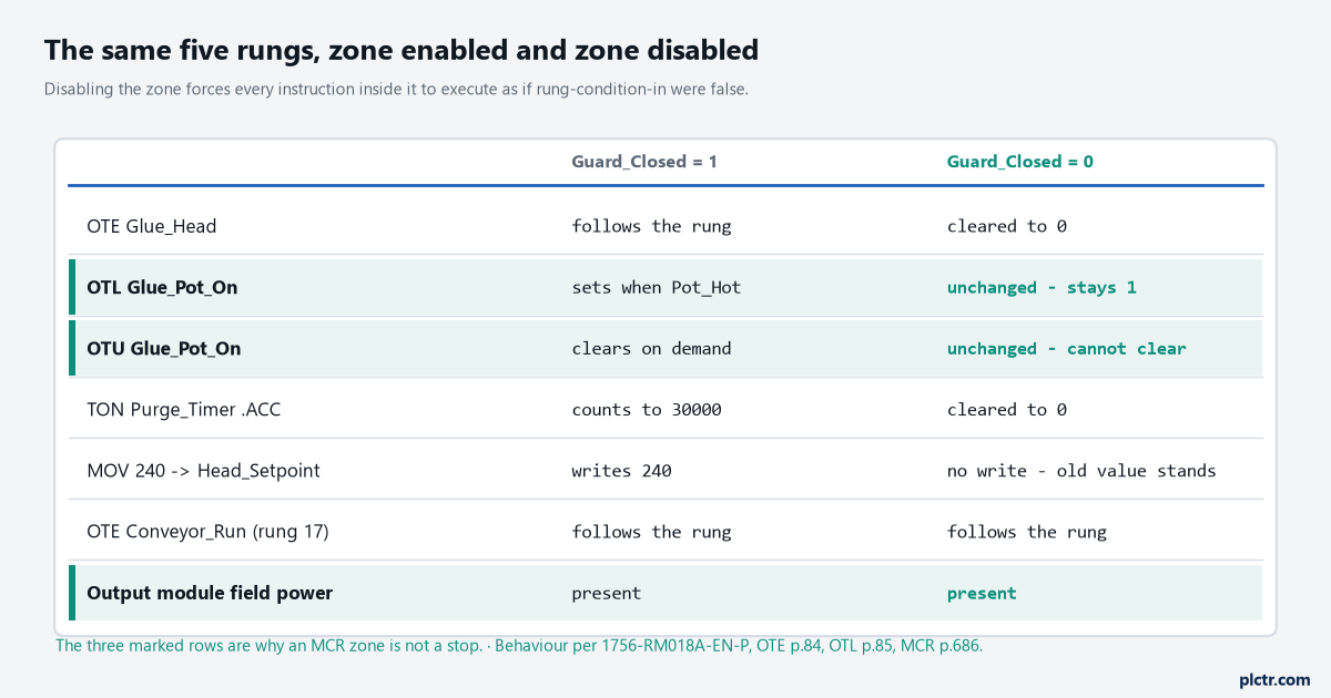
The three marked rows are the whole argument. The OTL holds, the OTU cannot clear it, and the module terminals are live either way.
What the real thing needs instead
Not an instruction. A circuit, a rated device, and an assessment sitting behind both.
The function that actually stops the hazard is built outside the program: a rated stop device, wired on two channels so a single short or a broken wire is detected, monitored for discrepancy between those channels, driving something that removes energy — a safety contactor, or the drive’s own Safe Torque Off input — with feedback from that final element through a mechanically linked auxiliary contact so the controller can tell whether the contactor really opened. Which architecture you need, and how much diagnostic coverage it has to have, comes out of the risk assessment for your machine and is expressed as a performance level under ISO 13849-1 or a SIL under IEC 62061; for a drive, the stop functions themselves are defined in IEC 61800-5-2. The standard-task ladder in your program can monitor all of it, log it, tell the operator about it. It cannot be it. We have separate write-ups on dual-channel wiring to PL d, on EDM and the mirror contact, on Safe Torque Off wired to a PowerFlex 755. Read those before you write the rung.
One more, because it comes up every time somebody moves relay logic into a controller: moving the same safety function from a 440R relay to GuardLogix sets out what the rung replaces and what it does not.
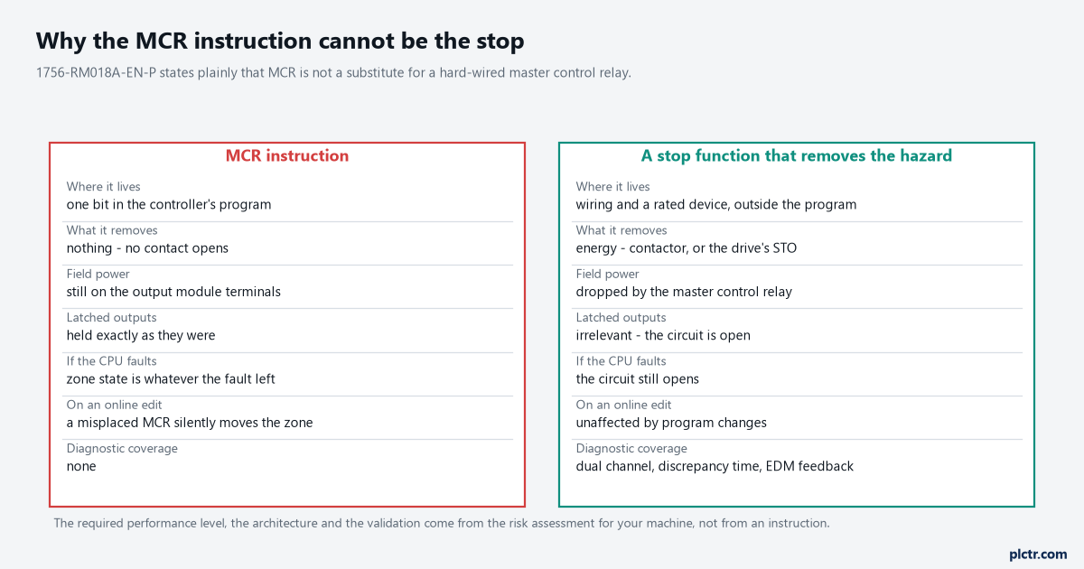
Left column is a bit in a data table. Right column is a circuit. Nothing in the left column survives a processor that has stopped executing.
JMP and LBL, which are usually what you wanted
Cheaper, clearer, and they only reach inside one routine.
JMP Skip_Fill on a true rung sends execution straight to the rung holding LBL Skip_Fill, and everything between the two is not scanned at all — no false execution, no cost, nothing. The label name can run to 40 characters of letters, numbers and the underscore; it has to be unique within the routine, and the LBL must be the first instruction on its rung. Both instructions must live in the same routine; you cannot jump into another one, which is what JSR is for. The jump also works backwards, and that is the one place JMP will hurt you: a backward jump repeats a block of logic inside the same scan, and enough repetitions will run the task past its watchdog and fault the controller. Studio 5000 will not let you download or accept an online edit if the JMP has no matching LBL, which catches the most common typo before it reaches the machine.
Jumped logic is not scanned. That sentence is in the manual as an IMPORTANT box and it is the whole risk: anything you need executed every scan — a heartbeat, a watchdog handshake, an alarm evaluation — has to sit outside the jumped block.
The traps that stay quiet
Four, and they all show up weeks later.
Do not jump into an MCR zone. If the JMP lands past the opening MCR, that rung never executes, the override bit is never toggled, and the zone is not disabled — so the logic somebody carefully switched off runs anyway. Do not condition the closing MCR: if the zone is enabled and the terminating MCR is false, it toggles the bit the wrong way and disables every rung after it to the end of the routine. Do not start a TON inside a zone you intend to drop, because the accumulator is cleared rather than held, and a purge timer that restarts from zero every time somebody opens a guard is a purge that never finishes. And remember the scope rules for the override bit: it resets when a subroutine or an Add-On Instruction returns, and an AOI invoked from inside a disabled zone runs its false-scan routine normally, with its own override bit, then hands the zone state back as it found it.
The nesting one deserves its own line. Two MCR pairs inside each other produce four toggles of one bit, not two zones.
The dead end everybody walks down first
When outputs behave oddly, the first move is usually to go hunting for a force.
It is almost never a force, and the force check takes thirty seconds to rule out, so do it and move on. The thing that actually catches an MCR problem is a cross-reference: pick the tag that is behaving wrongly, list every rung that writes it, and then look at which of those rungs sit inside a zone. Studio 5000 will tell you who writes a tag but it will not tell you that the writer is inside a disabled MCR zone — that you have to see for yourself, by opening the routine and looking for the pair. Cross-referencing a tag to find every rung that writes it covers the mechanics; the MCR part is on you. The second-best clue is a timer that keeps resetting, because a cleared accumulator in a zone you did not know existed is a very distinctive symptom once you have seen it once.
Next time you open a routine with an MCR pair in it, write down every OTL and OTU between the two, and decide for each one what you want it to do when the zone drops. If any answer is “it must go to a safe state”, that output does not belong in an MCR zone at all — it belongs on a circuit that opens. For what the controller itself is doing while all this happens, scan time and cycle time is the measurement to take.