Writing Your First Safety Routine: Standard Tags, Safety Tags, and the Mapping Between Them
Put a standard BOOL on a rung inside a safety routine and Studio 5000 will not accept it; the browse list does not even offer the tag. Try the obvious workaround next and the software refuses that too, because you cannot create a standard alias tag of a safety tag at all. The route in is safety tag mapping, under Logic then Map Safety Tags, which pairs one controller-scoped standard tag with one controller-scoped safety tag of the same data type and copies the value across at the start of every safety task execution. That is the whole mechanism, and the rest of this article is the five rules the dialog enforces, the one rule it cannot enforce, which is that the copied data is still not safety data, and the tags that the safety signature quietly leaves uninitialised. The controller is a GuardLogix 5580 and the manual is 1756-RM012J, September 2025.
Data crosses one way for free. Standard routines read controller-scoped safety tags directly, with no mapping at all.
What a safety program will hold
A safety program contains only safety components, and that sentence is stricter than it sounds.
Every routine in it is a safety routine, one of them is the main routine, another may be the fault routine, and a safety routine exists nowhere else. Safety routines are ladder diagram, the language choice does not appear, and they carry a watermark in the background so you know which kind you are editing without checking the properties. A safety program can define its own program-scoped safety tags, it can be scheduled or unscheduled, and it can hold no standard routine and no standard tag. Program parameters get their own restriction: a safety parameter cannot be connected or bound to a standard parameter or to a controller-scoped tag. All of which means the first thing a new safety program needs is not logic, it is a decision about which pieces of standard data have to reach it, because each of those becomes a mapping pair and each pair has to be created before the download rather than added later while you are commissioning. Mapping cannot be changed online in any of the states a commissioned machine spends its life in, so the cost of getting the list wrong is a trip back to Program mode.
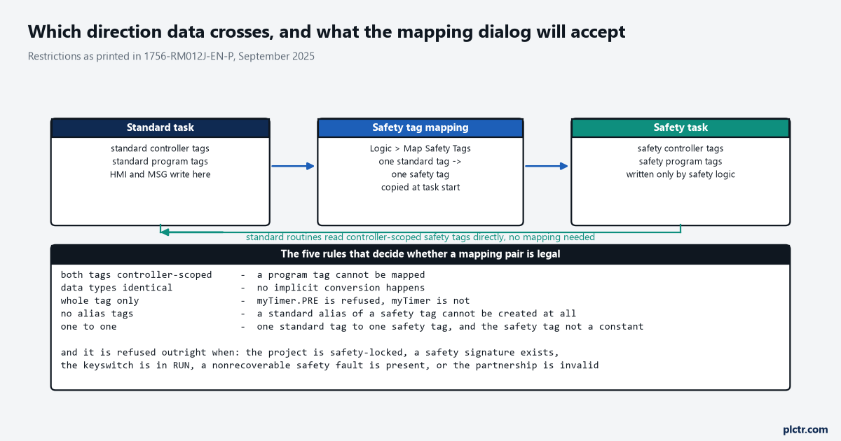
The middle box only ever copies left to right. The green path underneath is the one that needs no configuration and is the one people forget exists.
The five rules, and the five states
Both tags have to be controller-scoped. A program tag on either side is refused.
The data types have to match exactly, because nothing converts on the way across, and the safety side accepts only the primitives BOOL, SINT, INT, DINT, LINT and REAL, the predefined types the safety instructions use such as DCI_STOP and DCI_MONITOR, and user-defined types or arrays built from those; alias tags are not allowed on either side; the mapping has to be at whole-tag level, so myTimer can be mapped and myTimer.PRE
There is a cost to pay attention to. The copy runs every execution, and more pairs means a longer safety task scan.
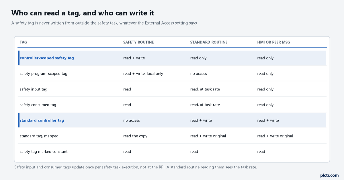
External Access can make a safety tag readable or not. It cannot make one writable: the controller refuses writes to safety tag data from HMI devices and from message instructions sent by peer controllers, full stop.
The one exception is the programming software itself. Logix Designer can write a safety tag directly through the Tag Monitor, and only while the controller is not safety-locked, has no safety signature and has no safety faults.
The copy is not safety data
This is the rule the dialog cannot check, and the manual puts an ATTENTION on it rather than a note.
Standard data in a safety tag is not safety data, and you must not directly control a SIL 2 or SIL 3 safety output with it. What you may do is let it permit something that safety data actuates, and the shape of that is worth copying exactly because the manual draws it: the mapped bit is qualified by a safety input, and there is a latch around it so a standard input failed in a stuck-at-1 state cannot restart the machine on its own. The reason the latch matters is that a mapped standard bit stuck at 1 looks identical, every scan, to an operator holding the button down: both are a level, and a level is what a restart must never be built on, the same argument that makes a safety reset a rising edge rather than a level. Take the edge with a ONS, latch the permit with OTL, and unlatch it from each safety function’s own output in its own rung: Gate_DCS.O1 in one, Estop_DCS.O1 in the next. Then the standard bit can only ever start something at the instant an operator actually asks for it, and it can never restart anything by having failed high while the guard was open.
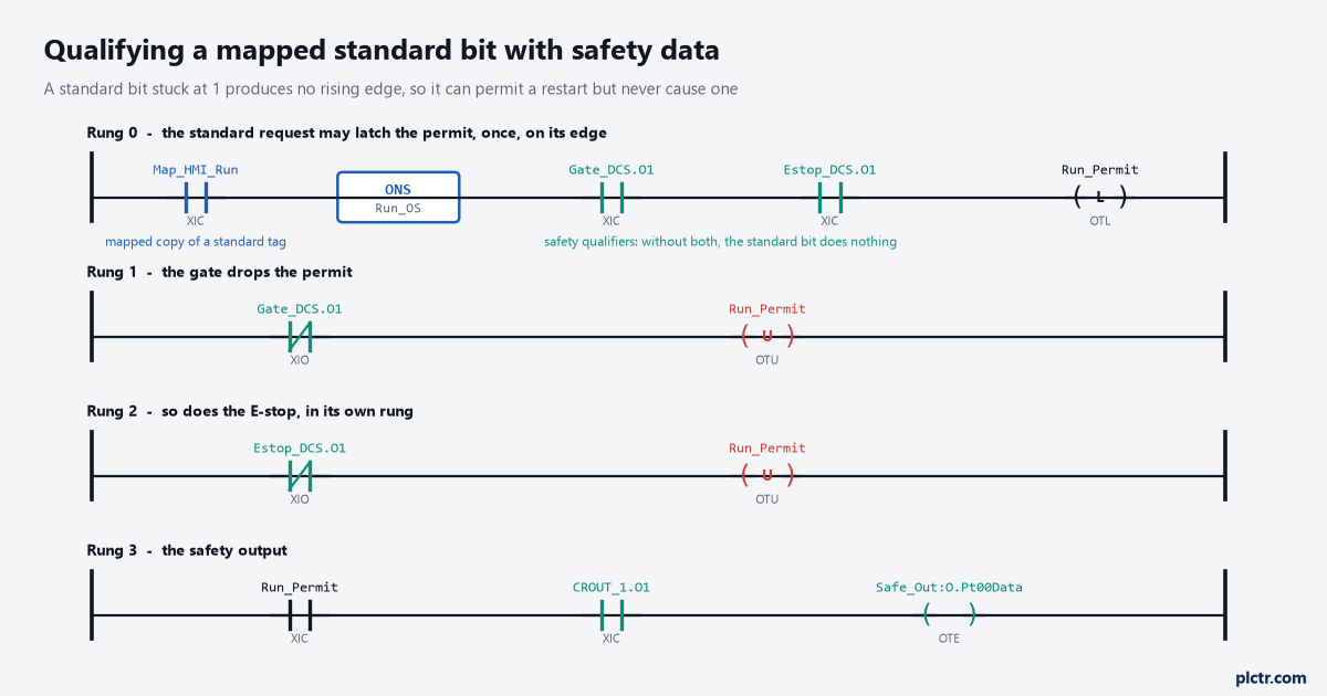
The two unlatch rungs are separate on purpose. Put both conditions in one rung and you need them both true to drop the permit, which is the opposite of what you want.
Notice what the standard bit does not touch. Rung 3 is driven entirely by safety data.
The tags the signature does not capture
Only safety tags configured as constant value tags are captured as part of the safety signature. Everything else starts at whatever the download left it.
That is fine for most tags and it is a real problem for pseudo-operands, because the preset of a TON, TOF, RTO, CTD or CTU and the length of a FAL or FSC are initialised once, when the application is downloaded, and not again on the next transition to Run unless your own code does it. If a safety-critical decision rests on one of those values, the manual is explicit that you must initialise it before the controller reaches Run mode, using a first-scan subroutine or an Add-On Instruction prescan routine. The pattern Rockwell documents is a snapshot: a routine that copies the working values of the non-constant safety tags into a backup structure once, when you are satisfied with them, and an Add-On Instruction whose prescan logic restores that structure on every subsequent transition into Run. If you write safety Add-On Instructions of your own, the same obligation applies inside them, and the AOI additionally carries a safety instruction signature that is checked when the project is downloaded.
The thing everyone tries first
An alias. It is the natural move, it takes four seconds, and aliasing is the one route the software closes deliberately here.
The second attempt is usually a MSG instruction from the standard task writing into the safety tag, which fails for the same underlying reason: the controller does not allow writes to safety tag data from message instructions sent by peer controllers, or from an HMI, regardless of what External Access says. The third attempt is a safety routine reading the standard tag through a JSR into a standard routine, and a safety program cannot execute standard routines. All three fail because there is exactly one door, it is the mapping table, and it copies in one direction at one moment in the scan. Once you accept that, the design question stops being how to get the data in and becomes which structure to map, which is a much better question to be asking.
Next step
List the standard values your safety logic will need before you create a single safety routine: the HMI run request, the mode selection, the recipe number if a safe speed depends on it. Build them into one user-defined type – Std_To_Safety with members RunRequest, ModeSelect, RecipeSpeedLimit and four spare BOOLs costs nothing today and saves a download in three weeks – create the standard tag and the safety tag of that type at controller scope, map the pair, and write the safety logic against the safety copy. While you are in there, check each safety input point on the module is configured single rather than Equivalent or Complementary, because the instructions provide the dual-channel handling themselves, including the cross-fault detection between the two channels and the instruction reference asks for the points to be set that way. The next article takes the first instruction most people put on those rungs, the E-stop, and the two different reset inputs it has.