Comparing REAL Values on a ControlLogix: Why EQU Is the Wrong Instruction
Page 882 of 1756-RM018A carries a worked example nobody quotes: subtract 10 from 10.1 on a Logix controller and the result could very well be 0.10000038, rather than the 0.1 you were expecting. Two pages of guidance later the same manual puts it as an instruction rather than a caution — do not compare floating-point numbers, check for values within a range instead, and the LIMIT instruction is provided specifically for this purpose.
That is Rockwell’s own answer to the question in the title, printed in the reference for the instruction set. The rest of this is why it is true and what a sensible band looks like.
EQU asks whether two 32-bit patterns are identical. It is a perfectly good instruction for a DINT step number or a recipe ID, and it is the wrong tool the moment either operand is a REAL, because a REAL almost never holds the number you think you put in it.
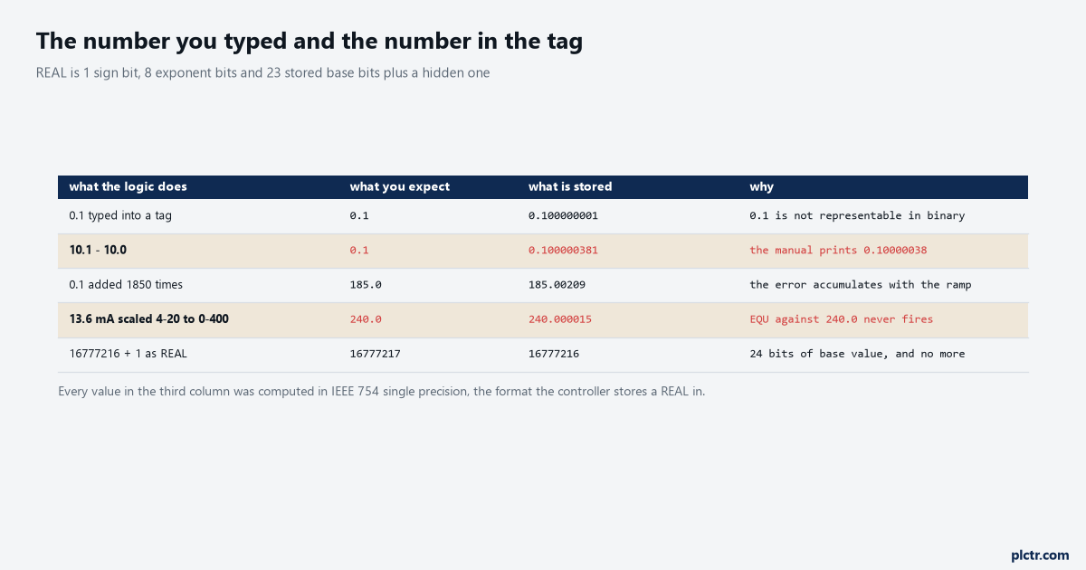
Every figure in the third column was computed in IEEE 754 single precision. The second row is the manual’s own example, to four more digits than it prints.
What a REAL is actually holding
One sign bit, eight exponent bits, twenty-three stored base bits and a hidden twenty-fourth.
That is the whole format, and it means a REAL can represent any number of the form (some 24-bit integer) times (a power of two).
0.5 is exact. 0.25 is exact. And 240.0 is exact, because it is 15 times 16.
0.1 is not, in the same way that one third is not exact in decimal no matter how many digits you allow — so the tag you typed 0.1 into is holding 0.100000001490116119384765625, and the controller rounds that to 0.1 on the screen because showing you the truth would be unhelpful nine times out of ten.
The tenth time is the one that costs you a morning.
Two places that error stops being invisible, both of them common. The first is accumulation: a setpoint ramped by adding 0.1 every execution reaches 185.00209 after 1850 additions, not 185.0, because each addition rounds and the roundings do not cancel. That is 2 millidegrees of error, which matters to nothing except an EQU looking for exactly 185.0, and it will be looking forever. The second is scaling. A thermocouple at 13.6 mA on a channel scaled 4-20 mA to 0-400 °C gives you 240.000015, not 240.0 — the arithmetic is a subtraction, a division and a multiplication, and every one of them rounds. The raw-count side of that arithmetic is worked through in reading a 4-20 mA transmitter into a 1756-IF8, and none of it is wrong. It is just not equal to 240.0.
There is a third place, and the manual is unusually direct about it: do not use floating-point math for money values or for totalisers. Add 1 to a REAL repeatedly and at 16777216 the addition simply stops having any effect, because there are no bits left to record it.
The manual’s workaround is a small accumulator rolled into a large one at a round number. Worth knowing before you build a shift totaliser on a REAL.
EQU, EQ, and the NAN that makes it false forever
A naming change first, because it will confuse you when you open a newer project.
In Logix Designer version 36 the mnemonic for this instruction changed from EQU to EQ, and LIM changed to LIMIT at the same time. Same instructions, same behaviour, new names, and older projects keep showing the old ones. If you are searching a manual and cannot find EQU, that is why.
Now the behaviour that surprises people.
The ladder execution row for EQ does not say “true if Source A equals Source B”. It says true if Source A and Source B are not NANs and Source A is equal to Source B — otherwise clear the rung. So the instruction has a third outcome hiding behind a BOOL, and you cannot see which one you got. A broken thermocouple that pushes an analogue channel into an overrange, a division by zero three rungs up, a SQRT on a negative number: any of those can produce a NAN, and from that moment your At_Setpoint bit is false and will stay false no matter what the setpoint does. Studio 5000 shows the value as 1#.NAN with no sign, which is the one clue you get, and you only get it if you look at the tag rather than the bit.
LIMIT handles the same case the same way — any operand NAN and .EnableOut is cleared — so it does not rescue you from a NAN, it just fails identically.
What it rescues you from is the width of the question, which is the next section.
Two other facts from the same page are worth carrying.
Denormalised numbers and negative zero are both treated as 0.0, so a comparison against 0.0 is one of the few that behaves. And if you are mixing a DINT into the comparison, a DINT needing more than 24 significant bits may not convert to the same REAL, with the controller storing the uppermost 24 bits rounded to the nearest even value. An encoder count above 16.7 million compared against a REAL is doing something you did not ask for.
The rung that replaces it
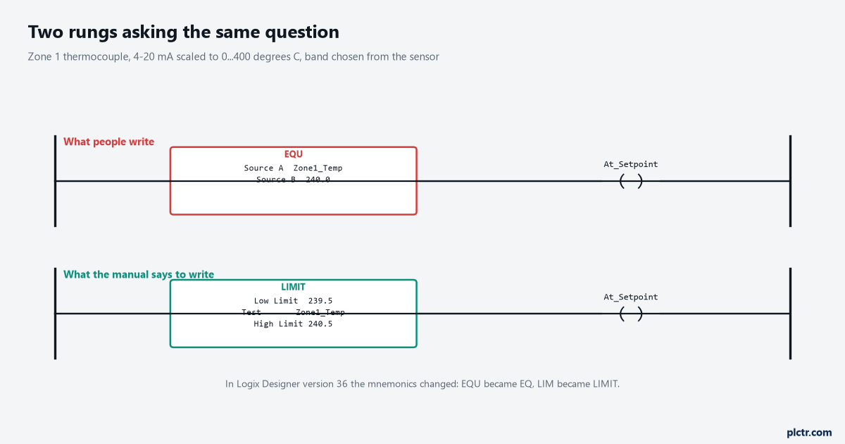
Same question, same coil. The lower rung is the one that can be true.
LIMIT takes three operands — Low Limit, Test and High Limit — and is true when the test value is equal to or between them. That is the whole instruction for the normal case, and the normal case is what you want almost every time. It is the same instruction that keeps a negative number out of a timer preset in TON, TOF and RTO on a false rung, which is worth knowing because once you start using it as a guard you find places for it.
Choosing the two limits is the part that deserves thought, and the honest rule is that the band comes from the measurement, not from the float.
A tolerance of plus or minus 0.0001 makes the rounding go away and makes the comparison meaningless, because a type K thermocouple through a 1756-IF8 is not accurate to a ten-thousandth of a degree and never was. Ask instead what “at setpoint” means to the process: a zone that has to sit within half a degree gets a band of 239.5 to 240.5, and a level that has to be within 2% of 1800 litres gets 1764 to 1836. Now the rung says something a process engineer can check, the float error is three orders of magnitude inside it, and the bit means what its name says. Put the two limits in named constants or a UDT beside the setpoint rather than typing them into the rung, because the next person to change the setpoint has to change them too and will not read your rung comment.
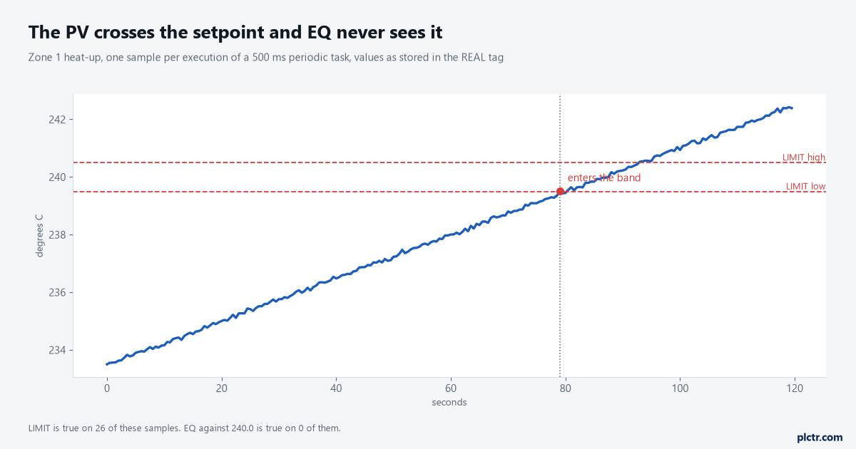
Twenty-six samples in the band, none of them exactly 240.0. The EQU rung is not intermittent; it is never true.
The trap in LIMIT nobody warns you about
LIMIT has a second mode, and you get it by accident.
If the Low Limit is greater than the High Limit, the instruction does not error and it does not return false. It inverts: the manual describes it as a circular number line, starting at the Low Limit and running clockwise to the High Limit, and the test is true for anything in that clockwise range — which for a low above a high means everything outside the band rather than inside it.
That is deliberate, and it is genuinely useful for a wrapping quantity such as an angle, where 350 to 10 is a real range that crosses zero.
It is a disaster when your two limits are tags.
Setpoint minus tolerance and setpoint plus tolerance are always the right way round. Setpoint times 0.98 and setpoint times 1.02 are the right way round until the setpoint goes negative.
So if either limit is computed at runtime, test the negative case before you leave site, or clamp the setpoint to positive values where the process allows it. A LIMIT that silently inverts gives you an At_Setpoint bit that is true everywhere except at the setpoint, which is the kind of fault that gets blamed on the sensor for a fortnight.
When EQU is still right
None of this makes EQU a bad instruction. It makes it an integer instruction.
Step numbers, recipe IDs, mode words, a Seq.POS from a sequencer, a fault code read out of a drive — all of those are exact values in exact storage, and comparing them for equality is what equality is for. The rule that is easy to remember and hard to get wrong: if the tag came from a sensor or from arithmetic, compare it with LIMIT; if it came from a number somebody chose, compare it with EQU.
The awkward middle case is a REAL that only ever holds values somebody chose.
A recipe temperature written from an HMI as 240.0, stored in a REAL, and compared against 240.0 will match, because both sides took the same trip through the same rounding and landed on the same bit pattern.
That works, and people build on it, and it keeps working right up until the value passes through one arithmetic operation — a unit conversion, an offset, a copy through a scaling block — after which the two sides diverge in the last bits and the comparison fails with no visible cause. Treat a REAL that has been through arithmetic as measured data, whatever its origin.
And if you genuinely need exact comparison of a fractional value, the answer is not a bigger float. LREAL doubles the precision and moves the problem rather than fixing it, and it is not available everywhere — the operand tables list it for the CompactLogix 5380, ControlLogix 5580 and 5590 and their GuardLogix equivalents, and not for the 5370 and 5570 families.
Scale to an integer instead. Store tenths of a degree in a DINT and compare 2400 against 2400, which is exact by construction.
What to check next
Cross-reference every EQU in the project and look at the data type of both operands, which takes about ten minutes and will find the ones that have been quietly false since commissioning. Then put the tag on a trend rather than a watch window and read the value at full precision — Studio 5000 rounds the display, and the number you are chasing is in the digits it is not showing you. If the comparison drives a loop’s at-setpoint logic, the gains and the units around it are worth a second look too, and PIDE gains, units and the first bump test covers that side. If it drives an output, the clamping decisions are in an analogue output that drives a valve. And if the value you are comparing is a setpoint that moves, the accumulated rounding in this article is exactly what a hand-written ramp produces and an RLIM does not — that argument is in RMPS and RLIM for ramping a setpoint.