Modbus TCP from a 1756-EN2T with the Socket Object: the Five Messages, the Frame, the Byte Order
A 1756-EN2T in slot 3 at 192.168.1.10, a third-party power meter at 192.168.1.40 answering on port 502, and a MSG instruction that returns 16#00ff with an extended code of 16#0000_0046 on every attempt. Nothing on that network is broken. The socket object on the 1756-EN2T is a raw TCP socket and nothing more, so the controller has to build the Modbus frame itself, byte by byte, in a SINT array, and has to run five separate CIP Generic messages in the right order to get one register value back. The Add-On Instruction that everyone ends up writing exists to hold that order, not to make the protocol easier.
Class 342 hex, five service codes, a twelve-byte request built by hand. That is the whole interface.
What the socket object gives you, and what it refuses to do
The EtherNet/IP Socket Interface application technique is blunt about the scope: the module has no application protocol knowledge, and makes only the socket services available to programs in the controller.
So there is no Modbus in a 1756-EN2T. There is a TCP socket, and Modbus is something your ladder writes into it. The services are reached with a CIP Generic MSG at class 342 hex, and they are Socket Create (service 4B), OpenConnection (4C), ReadSocket (4D), WriteSocket (4E), DeleteSocket (4F) and AcceptConnection (50), with Socket Create called against instance 0 and every later service called against the instance number that Socket Create hands back in a DINT. A 1756-EN2x carries 20 socket instances, against 32 on a 5580 or 5380 controller front port, which matters the moment someone asks for sixteen meters on one module and a spare instance for a scale. The communication path is 1, 3 for a module in slot 3 and the manual states that the message must reach the module over the backplane; you cannot send it to the module’s own IP address. Leave Connected cleared. The messages programming manual recommends CIP Generic messages stay unconnected for most applications, and the socket manual makes it mandatory when the front port of a controller is the target.
The instance number is returned, not chosen. Move it into the .Instance field of the other four MSG tags with a MOV.
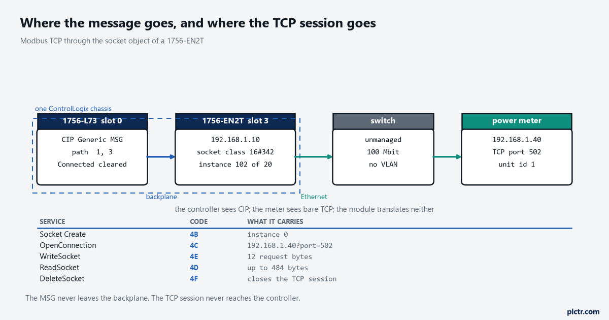
The MSG goes to the module across the backplane, never to the module’s IP address. Everything to the right of the module is plain TCP that the 1756-EN2T does not interpret.
The frame you have to build yourself
A Modbus TCP request to read holding registers is twelve bytes, and every one of them is yours to place.
The first seven are the MBAP header: a two-byte transaction identifier you echo back to match a response to a request, a two-byte protocol identifier that is always zero, a two-byte length count of everything that follows it, and a one-byte unit identifier. Then comes the function code, 03 for read holding registers, a two-byte starting address and a two-byte register count. Modbus puts the high byte of every sixteen-bit field first. Logix does not: the socket manual says application data has no inherent byte order and is sent exactly as given, but that Logix 5000 controllers store data in CIP byte order, little-endian, so a DINT or an INT written into the buffer arrives at the meter with its bytes reversed. Building the request as individual SINTs sidesteps that completely, because a SINT has no byte order to get wrong. Reading the response is where it bites. A response carrying two registers is thirteen bytes — seven of MBAP header, the function code echoed back, a byte count of 4, then the four data bytes — so the register values land in bytes 9 through 12, high byte first, and a COP
Swap the pairs on the way in. One SWPB per register, or a copy loop that moves byte 9 into the high half and byte 10 into the low half.
A worked example: unit 1, transaction 7, read two registers starting at 40001. Modbus addresses are zero-based on the wire, so the starting address field holds 0, not 40001, and that single off-by-one costs more debugging hours on a first commissioning than the byte order does.
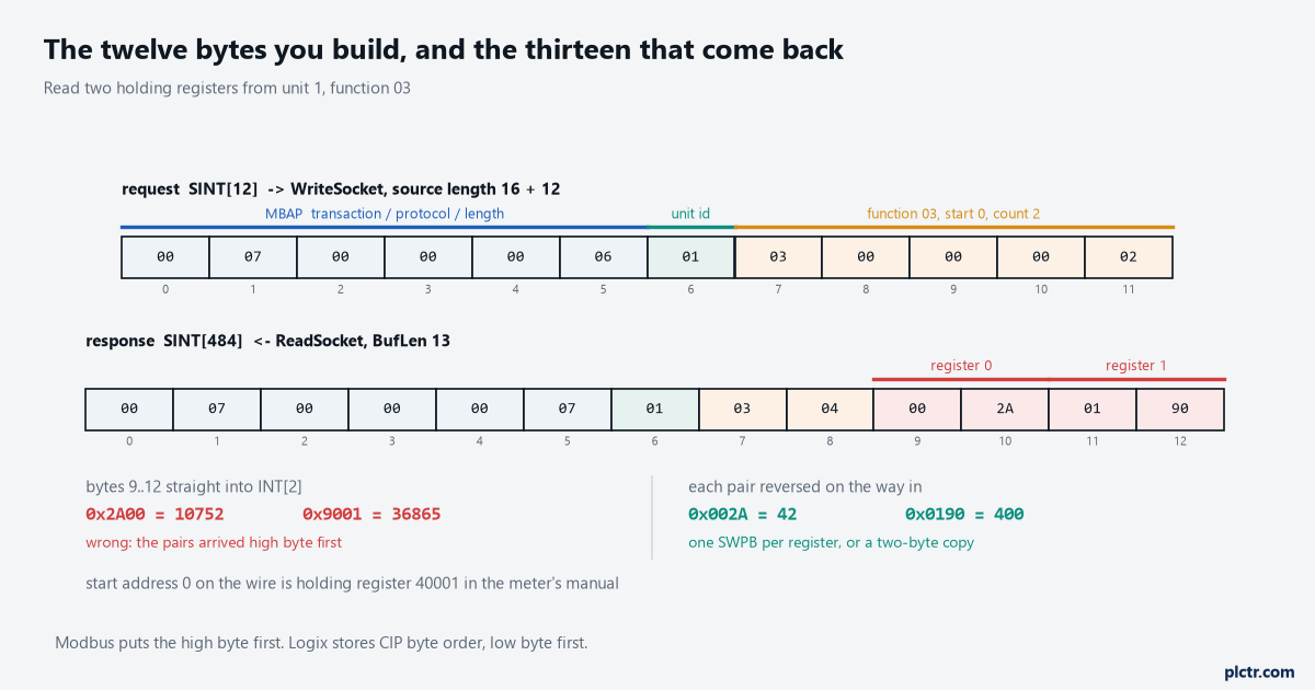
The request bytes go out in the order drawn. The response comes back in the same order and the two register pairs are reversed before the values mean anything to the controller.
The five messages, and why they end up in an AOI
Wrapping this in an Add-On Instruction is not tidiness. It is the only way to give each meter its own copy of a sequence that must not overlap.
The socket manual states the interlock in one line: user code must manage messages so that only one message to a socket instance is active at a time, and the read and the write for a given socket must be interlocked so only one executes at a time. That is a state machine — create, open, write, read, back to write — with a step number, a fault step, and a retry path that deletes the instance before it creates a new one. And the moment you try to put that state machine in an Add-On Instruction you meet the rule that shapes the whole design. The Add-On Instructions programming manual permits the MSG instruction inside an instruction, with a condition: the data instances must be passed as InOut parameters. MESSAGE is on the short list of data types you cannot use for a local tag, alongside ALARM_ANALOG, ALARM_DIGITAL, MODULE and the motion types. So the instruction cannot own its own messages. Five MESSAGE tags per meter get declared at controller scope, wired into five InOut parameters, and configured individually in the Message Configuration dialog of each one — because the path and the service code live in the MESSAGE tag, not in your parameters.
That is five controller-scope tags per device. Eight meters is forty MESSAGE tags, and a naming rule you will want before the fourth one.
Source lengths are exact and the module rejects anything else. Socket Create sends twelve bytes; OpenConnection sends eight plus the length of the destination string, which is written 192.168.1.40?port=502 and capped at 64 characters; ReadSocket sends eight, a DINT timeout and a DINT byte count; WriteSocket sends sixteen plus the number of bytes being written. The write length is the one that catches people, and the manual has a dedicated error for it: source length that is not exactly the buffer length plus sixteen comes back as 16#0013 or 16#0015, and a source length under seventeen bytes as 16#0020.
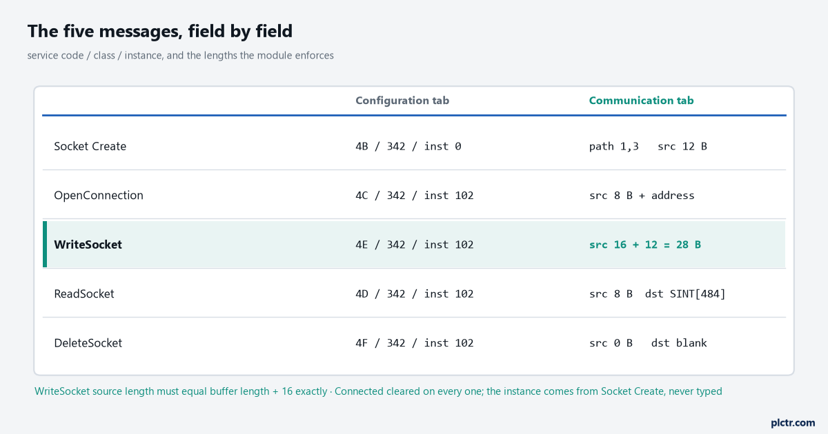
Only the Instance column changes between Socket Create and the rest. The source length column is the one that produces errors rather than silence when it is wrong.
The read that comes back short
TCP is a byte stream with no message boundaries, and the socket object hands you exactly that.
The socket manual warns that a read service can return a BufLen smaller than the amount of data requested, and that if the read times out before any data arrives at all, a BufLen of 0 comes back with a status of success and the MSG .DN bit set. Both of those look like a healthy message in the Logix Designer status bar. The first one leaves your INT array holding half a response and the other half of the previous one; the second leaves it holding stale values that never update, which on a power meter reads as a load that has been perfectly constant since Tuesday. The fix is the loop the manual prints as Structured Text: copy ReadResponse.Buf[0] into your assembly buffer at the current offset, add ReadResponse.BufLen to the offset, and issue another read for the remainder until the offset reaches the length the MBAP header told you to expect. Never act on the registers before the byte count is complete.
Watch BufLen, not .DN. A done bit on a socket read means the service finished, not that data arrived.
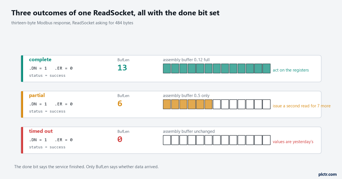
All three set the done bit. Only the byte count tells them apart, and the third one is the case that leaves a power meter reading a perfectly constant load.
When it errors, and the thing everyone checks first
Extended code 16#0000_0046 on the OpenConnection service is a socket timeout, and the manual lists three causes for it: the server IP exists but the port does not, the IP and the port exist but nothing is accepting connections there, or the service timeout in your UDT was left at zero or something close to it. None of those is a cable.
The cable is what gets checked first, along with the switch, the subnet mask and the meter’s own Ethernet LED — and it is almost never any of them, because the packet reached the meter and the meter closed the door. Ping the meter from a laptop on the same subnet, then open a TCP session to port 502 from that laptop before touching the panel. If the laptop gets in and the controller does not, the difference is in the MSG, and the shortlist is short: 16#0005 with extended 16#0000_0000 or 16#0000_0001 means the socket instance does not exist, which after a working start usually means the five-minute inactivity timeout deleted it while the poll rate sat at ten minutes; 16#0002 means a read and a write hit the same instance in the same scan and the interlock is not doing its job; 16#0009 is an invalid socket descriptor, and for a UDP read or write it is usually the Family member left at 0 instead of 2. Extended 16#0000_0030 on Socket Create is the local port already in use, which happens when a retry path creates before it deletes.
Raise the inactivity timeout with a Set Attribute Single on instance attribute 7 rather than polling faster than you need to.
What to do next
Put a scope on the sequence before you write the AOI: one Socket Create, one OpenConnection, one WriteSocket and one ReadSocket, triggered by hand from the tag editor, with the twelve request bytes typed in as literals. When those four return without an error and the response byte count matches the header, the protocol is proven and everything after that is state machine work. The state machine is the part worth reviewing against ControlLogix ladder troubleshooting once it is running, and the UDTs for the request and response parameters are worth building properly from the start — UDT usage examples covers the shape. If the device on the far end speaks EtherNet/IP after all, none of this applies and the EtherNet/IP setup and RPI article is the shorter road. For the wrapper itself, creating an Add-On Instruction in Studio 5000 is where the five InOut parameters get declared.