The Connection Timeout Multiplier on a 1756-EN2T: What It Buys and What It Hides
A rack-optimised connection through a 1756-EN2T at a 100 ms RPI rides out 400 ms of total silence before the module goes yellow in the I/O tree. At a 10 ms RPI the same connection faults after 160 ms, not after 40. The multiplier that produces those numbers has no box on the Connection tab, no entry in the module properties, and no way to change it, because the controller firmware picks it — and the rule it picks by is printed in one paragraph of the EtherNet/IP Network Devices user manual.
An implicit message times out in multiplier × RPI, the multiplier is chosen so that the timeout lands at 100 ms or more, and the smallest multiplier it will use is 4.
The rule, and the two numbers the manual works out
Everything about I/O fault detection on an EtherNet/IP connection follows from that one sentence, and the manual backs it with two examples that pin down how the multiplier moves.
At an RPI of 2 ms the controller multiplier comes out at 64 and the timeout at 128 ms. At an RPI of 10 ms the multiplier is 16 and the timeout is 160 ms. Both land just past 100, both multipliers are powers of two, and both are the smallest power of two at or above 4 that gets the product over the line. Work the rest of the range the same way and the table it produces is the useful part of this article: 4 ms RPI gives ×32 and 128 ms, 20 ms gives ×8 and 160 ms, 25 ms gives ×4 and exactly 100 ms, and from 25 ms upward the multiplier is stuck at its minimum of 4 and the timeout simply tracks the RPI. So the detection time is not proportional to the RPI anywhere below 25 ms, and above it the relationship is a flat factor of four.
Below a 25 ms RPI you are buying data rate, not fault detection.
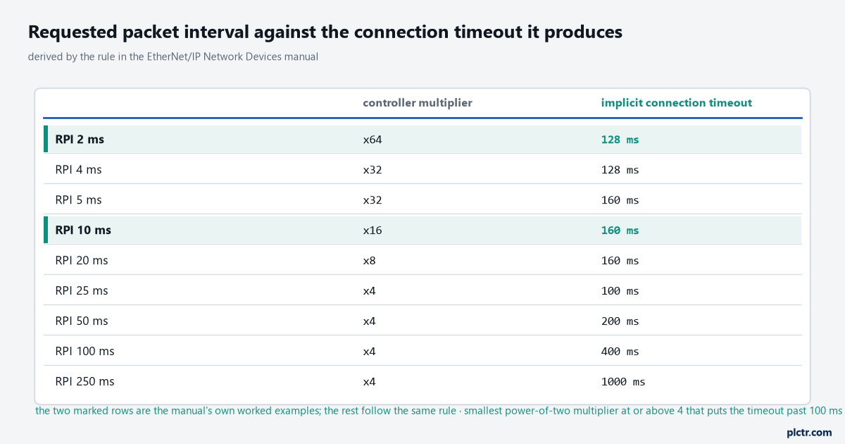
Every row below 25 ms is derived by applying the manual’s rule: the smallest power-of-two multiplier at or above 4 that puts the timeout past 100 ms. The two marked rows are the manual’s own arithmetic and the derivation reproduces both.
What the multiplier buys
The multiplier exists so that one dropped frame on a UDP connection does not stop a machine.
Implicit I/O is unacknowledged UDP, which means there is no retry and no ordering. A frame that a switch drops during a broadcast storm, a frame that arrives late behind a large explicit transfer, a frame lost while a port renegotiates — none of these is a fault, and a connection that dropped on the first missed packet would fault several times a shift on a network that is behaving normally. At a 10 ms RPI the ×16 multiplier means fifteen consecutive packets can go missing and the connection carries on as if nothing happened, with the input data in the controller tags simply not updating during that window. That ride-through is why a Stratix reboot in the middle of a shift often costs nothing at all, and why the same reboot on a connection running at 250 ms RPI produces a full second of stale data that nobody sees. The design consideration underneath it is that I/O data is a value with an age, not an event.
Fifteen missed packets, no fault, no log entry, no evidence. That is the deal the multiplier makes on your behalf.
What it hides
Stale data reads exactly like fresh data. Nothing in the input tag says how old it is.
A drop shorter than the timeout leaves no trace anywhere a controls engineer normally looks: the module has no fault code, the I/O tree has no yellow triangle, the controller log is empty, and the connection status bits in the module’s input tag never changed state. Meanwhile the operator saw a photoeye that “stuck on” for half a second and a reject that should not have happened. On a 100 ms RPI rack-optimised connection through a 1756-EN2T that window is 400 ms wide, and a 400 ms window is long enough to miss a carton on a 60 m/min belt by a quarter of a metre. The failure mode is worst exactly where people set the RPI most casually, on a rack of digital inputs where 100 ms felt generous. And it compounds with the change-of-state behaviour the design considerations manual describes: with change of state enabled the module produces every RPI when nothing changes, and at a maximum rate of RPI/4 when data does change, so a burst of activity puts four times as many frames on the wire in the same interval as a quiet period.
If a fault window matters to the process, the number to write on the drawing is the timeout, not the RPI.
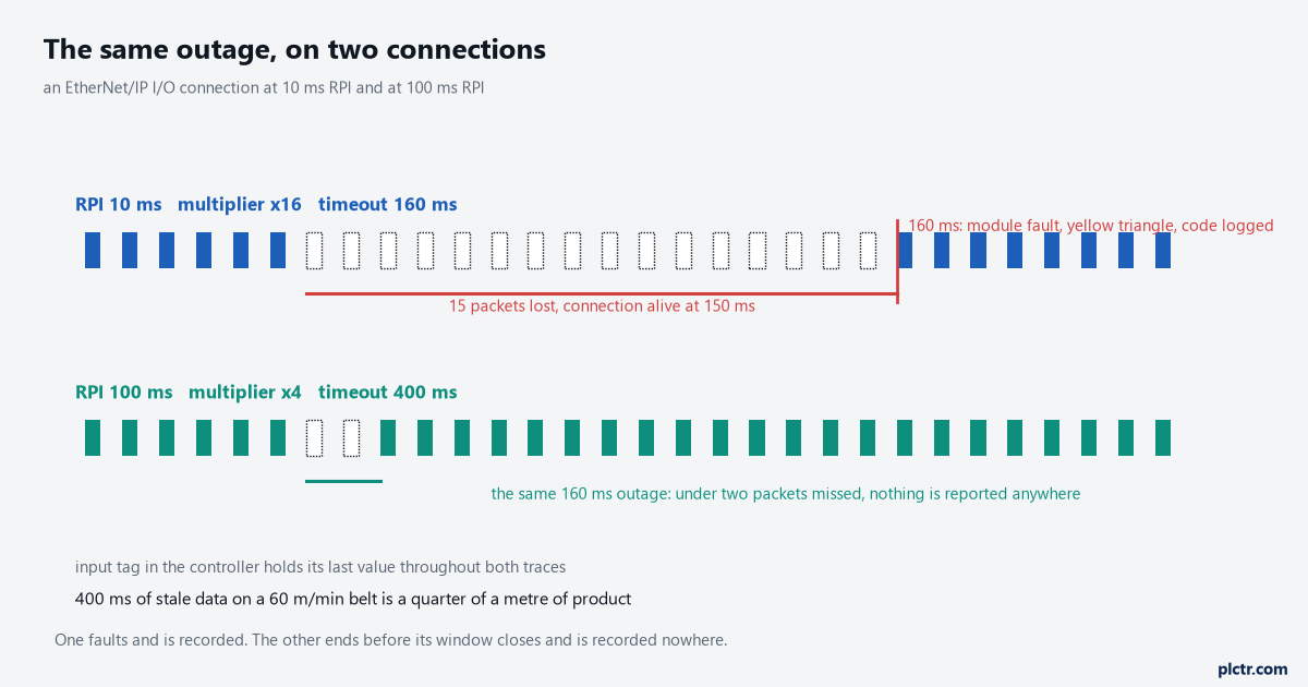
The top trace faults and produces a module fault code. The bottom trace, with the same physical outage, ends before its 400 ms window closes and reports nothing at all.
Where people go looking for the field, and what is actually on that tab
The Connection tab of a module’s properties holds four things that matter, and a multiplier is not among them.
There is the Requested Packet Interval, in milliseconds, which is the only number in this whole mechanism you control. There is Inhibit Module, which closes the connection deliberately and is the honest way to take a module out of service. There is Major Fault On Controller If Connection Fails While In Run Mode, which converts a connection loss into a controller major fault and is the setting people reach for when they want the loss to be unmissable. And there is the unicast checkbox, which decides how the packets are addressed rather than how long they may be missing. The search for a timeout multiplier usually ends with someone finding one on a CIP Safety connection — safety connections do expose a timeout multiplier and a network delay multiplier, because a safety reaction time has to be calculated and justified — and then assuming standard I/O has the same control hidden somewhere. It does not. Standard I/O gives you the RPI and keeps the rest.
The one adjacent trap worth knowing: module fault 16#0111 is an RPI out of range, and on a listen-only connection it also means the owner’s RPI is slower than the one this controller asked for.
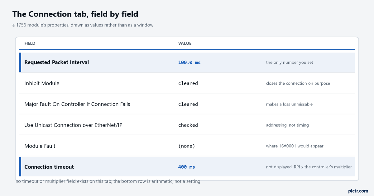
Four fields decide the behaviour and one of them is a number. The timeout in the footer is not displayed anywhere in the software; it is the RPI times the multiplier the controller chose.
Choosing an RPI once you know what it sets
Pick the RPI from the fault detection time the process needs, then check the bandwidth it costs, rather than the other way round.
A conveyor interlock that must stop within 200 ms of losing its inputs needs a timeout under 200 ms, which puts the RPI at 20 ms or below, and 20 ms on a rack-optimised digital connection is cheap. A tank level that updates on an HMI can sit at 250 ms and its one-second timeout harms nobody. A CompactLogix adds a wrinkle worth knowing before you compare two racks: the design considerations manual says those controllers transmit at powers of 2 ms, so an RPI typed as 100 ms actually transfers at 64 ms, and the connection that looked identical to the ControlLogix one on paper is running faster than either number on the drawing.
Write the timeout next to the RPI in the module list. It is the number the process cares about and the only one nobody can read off a screen.
What to do next
Open the I/O configuration tree, list every remote module with its RPI, and put the derived timeout beside each one — four times the RPI for anything at 25 ms or above, and off the table above for anything faster. Any module whose timeout is longer than the process can tolerate gets either a faster RPI or the Major Fault On Controller checkbox, and a rack of modules with no consistent answer is a design decision that was never made. From there, the reason to care about which modules are in which racks is covered in EtherNet/IP setup, RPI and faults, the fault codes that appear when a connection does time out are in Allen-Bradley I/O faults and their causes, and the switch behaviour that determines whether a lost packet is rare or routine is worth reading in PLC networking: switches, VLANs and DLR rings.