A Pt100 RTD input wired two-wire over 22 m of 0.5 mm² cable into channel 0 of a 1756-IR6I reads 104.1 °C in a bath that the reference thermometer says is 100.0 °C, and the same sensor with its third lead landed on RTN-0/C reads 100.0 °C. Lift lead A off the module and the channel reads 870.0 °C with Ch0Overrange set; lift lead B instead and it reads -200.0 °C with Ch0Underrange set. The same sensor on an SM 1231 RTD reads 1000 in the bath, because that module reports tenths of a degree, and 32767 with any lead lifted, which is the same number it uses for a real overflow.
The 4.1 °C is the cable. The 870.0, the -200.0 and the 32767 are the module telling you which wire is off, in a code each vendor prints in its manual and nobody reads until the trend goes vertical.
This was written against the ControlLogix analogue I/O manual 1756-UM009 and the S7-1200 system manual, with the S7-1500 analogue function manual for the wiring rules that the 1200 manual only draws. The readings in the open-lead table are the values those manuals say the modules substitute; the bath, the cable and the 22 m are a worked example.
What the third wire on a Pt100 RTD input is for
A resistance thermometer has no signal of its own. The module makes one.
Both vendors describe the same arrangement. The module drives a small constant current out through the sensor and measures the voltage the current produces across it; the S7-1200 manual gives the SM 1231’s current as 0.48 mA at 0 Ω falling to 0.34 mA at 4400 Ω, pulsed between the active channels so that with eight channels active each one sees it 12.5% of the time, and the S7-1500 function manual names the two terminals it leaves on, IC+ and IC-, and the two it measures at, M+ and M-. With two wires the current path and the measuring path are the same pair of conductors, so the voltage the module sees is the current times the sensor plus both leads, and the leads are copper that the module cannot tell from platinum. With three wires the current still flows out and back through two of them, but the third carries no current and lets the module measure the drop across one lead on its own and take it out. The function manual says it in one line: measurements with 4-wire or 3-wire connection compensate for line resistance, measurements with 2-wire connection always acquire it. What it asks in return is on the same page. Use cable with wires of identical cross-section, because the compensation assumes the lead it measures is the same as the lead it cannot.
Two wires carry the current. The third one carries nothing but the measurement.
The number the cable costs is small per metre and adds up. A Pt100 changes by about 0.385 Ω per degree, which is the 0.003850 coefficient both manuals name multiplied by the 100 Ω the sensor has at 0 °C, and a 0.5 mm² copper conductor is around 36 mΩ per metre on most cable datasheets. Twenty-two metres of two-wire is 44 m of copper, 1.58 Ω, 4.1 °C. Fifty metres is 3.6 Ω and 9.4 °C, and the error is the same at 0 °C as at 300 °C, so it does not disappear in a single-point calibration.
Three wires, one length, one gauge. The module does the subtraction; you supply the assumption.
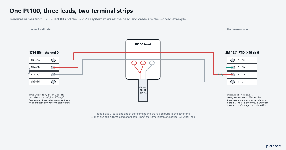
Two leads leave one end of the element and share a colour; the single lead is the other end. Which module pin each one lands on is the whole job.
Landing it on a 1756-IR6I
Three terminals per channel, and their names say what they do: IN-0/A, IN-0/B and RTN-0/C for channel 0.
The manual’s three-wire drawing puts the two same-colour leads on IN-0/A and IN-0/B and the single lead on RTN-0/C, with the shield to ground at the module end. For a two-wire sensor the manual is explicit that IN-x/B and RTN-x/C are shorted together at the terminal block, and a four-wire sensor is wired as three-wire with the fourth lead left open. Two rules sit under the drawing and both get broken: do not connect more than two wires to any single terminal, and if the channel is powered from a separate source do not exceed the isolation voltage. The module has no I+ and I- of its own; the current goes out on one terminal and returns on RTN, which is why a lifted lead behaves differently depending on which one it is.
Then the configuration, and this is where the ohms turn into degrees or do not. The 1756-IR6I linearises ohms into temperature only in floating point mode; the manual says integer mode does not support temperature conversion on the temperature-measuring modules, so a channel left in integer format gives you counts of resistance and nothing you can put on a trend in degrees. On the Configuration tab the Sensor Type list for a 100 Ω sensor offers Platinum 385, Platinum 3916 and Nickel 618, and the choice sets the linearisation and the limits: Platinum 385 runs -200.0 to 870.0 °C, Platinum 3916 stops at 630.0 °C. Temperature Units is one setting for all six channels. The 10 Ohm Copper Offset field, -0.99 to 0.99 Ω, is for copper sensors only and is left alone here. One trap on the same tab is the scaling. The manual’s default signal and engineering values for the module are 1 to 487, and it says the actual numbers are irrelevant as long as the low signal equals the low engineering value and the high signal equals the high engineering value; only then does the module send temperature over the whole sensor range. Somebody who tidies those fields to 0 and 100 because that looks like a temperature span has just told the module to rescale its temperature output, and the reading will be plausible and wrong.
Float mode, sensor type, units. Leave the four scaling numbers alone.
If the input is on a POINT I/O drop, the 1734-IR2 does the same job on a smaller strip: In 0/A, In 0/B and RET 0, with a two-wire sensor needing a 1 Ω resistor from In/B to RET according to the wiring figure in 1734-IN011, and the sensor list gives 100 Ω Pt 385 the same -200 to 870 °C. Its data arrives as an INT per channel with a status byte carrying overrange, underrange, the four alarm bits and a channel fault bit.
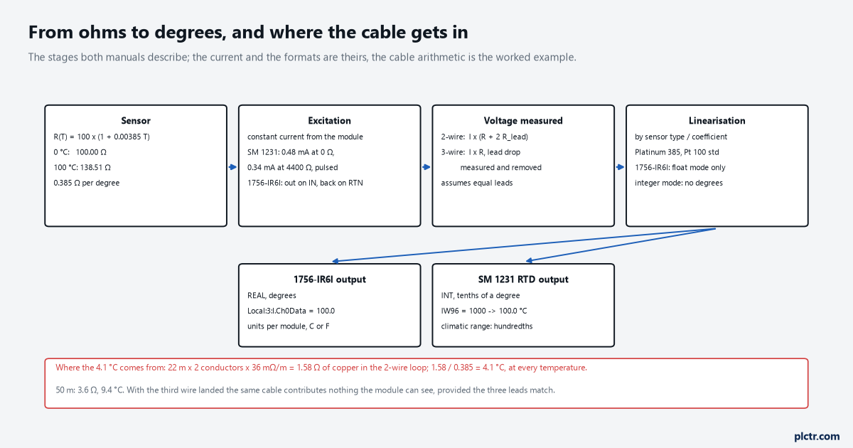
The 4.1 °C enters at the voltage stage and nowhere else. Everything after the ADC is arithmetic the module does from the sensor type you picked.
The same sensor on an SM 1231 RTD
Four pins per channel on the S7-1200 module, 6ES7231-5PD32-0XB0 for four channels, 6ES7231-5PF32-0XB0 for eight: M+, M-, I+ and I-, on pins 4 to 7 of X10 for channel 0.
The S7-1200 manual draws the two-, three- and four-wire arrangements in table A-179 and does not describe them in words, so the words come from the S7-1500 function manual, which covers the same four-terminal channel: wire the current lines and the measuring lines directly to the element for four-wire, and for three-wire on a four-terminal channel insert a bridge at the module between M- and I- or between M+ and I+. Check that against A-179 before landing it; the pin names are the same, the manual is the authority for the drawing. Two things the 1200 manual does say in words: the connectors must be gold, and unused channels should either be deactivated or wired with a loop-back resistor like a two-wire sensor, because a channel that is enabled and open adds stabilisation time to the whole module.
The measurement type is Thermal resistor, and the sensor is Pt 100 with the 0.003850 coefficient. The manual’s selection table gives the standard range a nominal span of -200.0 to 850.0 °C with an accuracy of ±0.5 °C at 25 °C ambient and ±1.0 °C over -20 to 60, and a climatic range of -120.00 to 145.00 °C at ±0.20 °C. The value comes back as an INT in tenths of a degree for the standard range, 253 for 25.3 °C, and in hundredths for the climatic range. Divide by ten on the way into a REAL and the job is done; the same scaling shape as any other analogue channel applies, with a constant instead of a span. The noise reduction setting, 10, 50, 60 or 400 Hz, sets the module update time; the wire resistance limit is 20 Ω per the specification table, and the cable is limited to 100 m.
Tenths of a degree in an INT, and a divide by ten on the way in.
Below the under-range minimum of -243.0 °C the module reports -32768. Above the over-range maximum of 1000.0 it reports 32767. Between 850.1 and 1000.0 it carries on reporting the value, so a steady 850.0 on an HMI is a real reading or an HMI limit, not a module clamp.
What an open lead reads, module by module
Nobody reads zero. Every one of these modules substitutes a value on an open circuit, and the value is chosen to be impossible.
On the 1756-IR6I the manual’s wire off table has two rows for the RTD module in temperature applications. When only the wire on terminal A is lost, the input changes to the highest scaled temperature value for the selected RTD type and ChxOverrange is set: 870.0 °C on Platinum 385. When any other combination of wires is disconnected, the input changes to the lowest scaled value and ChxUnderrange is set: -200.0 °C. So the substitute value names the wire. The same table carries the manual’s one important warning in a box: disabling all alarms on a channel also disables the underrange and overrange detection, and if alarms are disabled the only way to discover a wire off is from the input value itself. Disable only the channels that are unused.
The substitute value names the wire. The alarm bit says it is a substitute.
The 1734-IR2 keeps it to one rule. In any mode, if a broken or detached lead is detected, the data value is forced to maximum and the overrange alarm is set, and the alarm stays active for as long as the input is faulted.
The SM 1231 RTD is the one that needs a second look, because the manual says it returns 32767, 16#7FFF, for both a wire break and an overflow, and the specification table adds that with the wire break alarm disabled and a lead open the module may report random values. The module’s diagnostics do know the difference, and section 15.18 of the system manual gives the procedure for reading it: a diagnostic error interrupt OB, a RALRM call with the module’s hardware identifier at F_ID, and an AINFO byte array of at least 34 bytes, in which the word at bytes 32 and 33 reads 16#0006 for wire break and 16#0007 for high limit exceeded. Twelve lines of code, and a trend that says 3276.7 °C becomes an alarm that says which.
On an S7-1500 with the AI 8xU/I/RTD/TC ST, the module manual’s own table for the wire break event says the measured value is 32767 with the diagnostic enabled and that wire break takes priority over overflow and underflow, while with it disabled and underflow enabled the value leaves through the undershoot range to -32767 with a low limit violated alarm. The same manual has a line that catches people on their first RTD: the thermal resistor measuring types are configurable on the even channels only and the following odd channel has to be deactivated, so an eight-channel module carries four Pt100s.
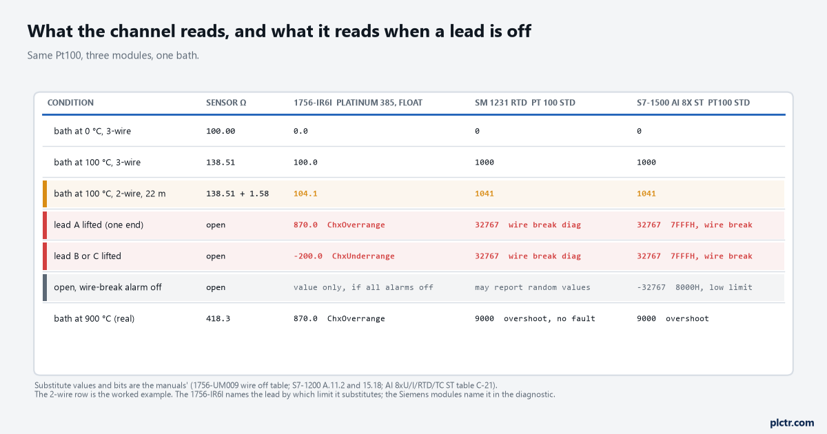
The substitute values are the manuals’; the two-wire row is the worked example. On the 1756-IR6I the value tells you which lead; on the Siemens modules the diagnostic does.
The thing everyone swaps first
The sensor.
Thirty seconds with a meter beats a new sensor and a day waiting for it.
A Pt100 is the last thing to change, because it is the one part of the loop a meter can prove in thirty seconds. At the head, between the single lead and either of the pair, the element reads 100 Ω at 0 °C and about 108 Ω at 20 °C, and between the two paired leads it reads the resistance of one lead, a fraction of an ohm. Read the same three pairs at the panel end of the cable with the module disconnected and the numbers should be the sensor’s plus the lead’s; a pair that reads open at the panel and closed at the head is the cable or the gland, and a pair that reads open at the head is the element, which happens, but far less often than the crimp. Only then look at the module, and look at the status bits before the value, because on the 1756-IR6I an underrange bit with a sensor that meters fine means a lead is on the wrong terminal, and a reading that changes by four degrees when the cable is warm in the sun means the third wire is not doing anything, usually because IN-0/B and RTN-0/C were shorted for a two-wire sensor that has three leads.
The meter reads the sensor. The status bit reads the wiring.
Next step
Meter the three pairs at the head and write the numbers on the loop sheet with the ambient temperature, then run three conductors of one cable to the module and land them by the manual’s drawing, not by colour. Set floating point, the sensor type and the units on the 1756-IR6I, or Thermal resistor, Pt 100 standard and the noise frequency on the SM 1231, and put the channel’s overrange and underrange bits on the alarm list before the value goes on a trend. Where the loop feeds control rather than display, the PID block wants the value in degrees and the status bit as a permissive, and the same open-lead substitute logic is worth reading for a 4-20 mA transmitter on a 1756-IF8, where under-range is a current rather than a resistance. If the input card is new to you, what sinking, sourcing and isolation mean on an I/O module is the page that explains why the RTD channel is isolated and the excitation current is its own.