An S7-1500 watch table gives you two ways to put a value on an address, and they behave nothing alike. A force job is written to the SIMATIC memory card and is retained after a POWER OFF, and while one is active the MAINT LED on the CPU sits lit yellow. A modify does none of that: it is an online function, it is not stored in the CPU, and it ends the moment you drop the connection.
That single difference answers most of the “why will this value not change” questions, so it is worth having straight before you open anything. The rest of this is the order of operations: get online properly, monitor the block, build the watch table, and then work out which of six or seven ordinary things is holding the number still.
The CPU here is a 1516-3 PN/DP, article number 6ES7516-3AN02-0AB0.
Dialog names are from STEP 7 Professional, and the behaviour below comes out of the S7-1500 system manual A5E03461182-AC and the equipment manual for that CPU. Where a detail is only written down for the S7-1200 the text says so rather than pretending it applies everywhere, because it sometimes does not: the S7-1200 force table cannot modify at all, and the S7-1500 one can.
Getting online, and what has to be true first
Two requirements, and the manual states both: there has to be an online connection to the CPU, and there has to be an executable user program in it. The second one is less obvious than it sounds on an S7-1500, because the program does not live where an S7-1200 person expects. A SIMATIC memory card is absolutely required in order to operate the CPU, and a user program transferred over an online connection is written to the load memory on that card. Pull the card and there is nothing to monitor.
Then the connection itself.
Select the CPU in the project tree, press Go online, and the first time you do it you pick the type of PG/PC interface and then the specific adapter. Once connected, the work area headers turn orange and the project tree shows a comparison of the offline project against the online CPU, with a green circle where the two agree.
Look at that circle before you look at anything else.
A watch table reading values out of a CPU whose program is not the program on your screen will tell you the truth about the CPU and lie to you about your logic. Twenty minutes later you are arguing with a network that is not the network running, and nothing about the watch table looks wrong, because nothing about the watch table is wrong. Check the circle.
Monitoring a block
Program status is where everybody starts.
Open the block, press Monitoring on/off, and the network colours itself according to power flow, so you can read the RLO along the rung instead of inferring it from the tag values.
Two things the manual says about it that are easy to skip.
The first is a cost. Monitoring loops can increase the cycle time significantly, and how much depends on the number of tags being monitored and on how many times the loop actually runs, so on a block with a nested FOR it is not a rounding error. The second is a warning, printed as a WARNING, and it deserves the capital letters: testing with program status can cause serious damage to property or injury to persons if there are functional disturbances or program errors, and you are supposed to make sure no dangerous situation can arise before you start. People run program status on a live machine constantly. The manual’s position on that is clear and mine is the same. Beyond those two, the limitation is practical: program status shows you one block, in one call, at whatever moment the CPU could answer, which makes it excellent for “is this rung true” and useless for “what happened four hundred milliseconds ago”.
The S7-1500 watch table, and what each address can actually do
Add new watch table, then type addresses or tag names into it.
The list of what it can reach is longer than most people use.
The S7-1500 system manual gives it as inputs and outputs through the process image, bit memory, the contents of data blocks, peripheral inputs and peripheral outputs, and timers and counters. It lists the same areas as modifiable. And it gives the watch table two functions that only work in STOP, Enable peripheral outputs and Modify now, which exist so you can put a value on an output and go and check the wiring with a meter rather than reasoning about it from the schematic. One column matters more than it looks, and it is the Name column: the manual notes that a symbolic name has to be entered there if you want the CPU display or the web server to show the value of the tag. An address-only watch table works fine on the laptop and shows nothing at all on the panel front, which is an awkward thing to discover after you have handed a machine over and gone home.
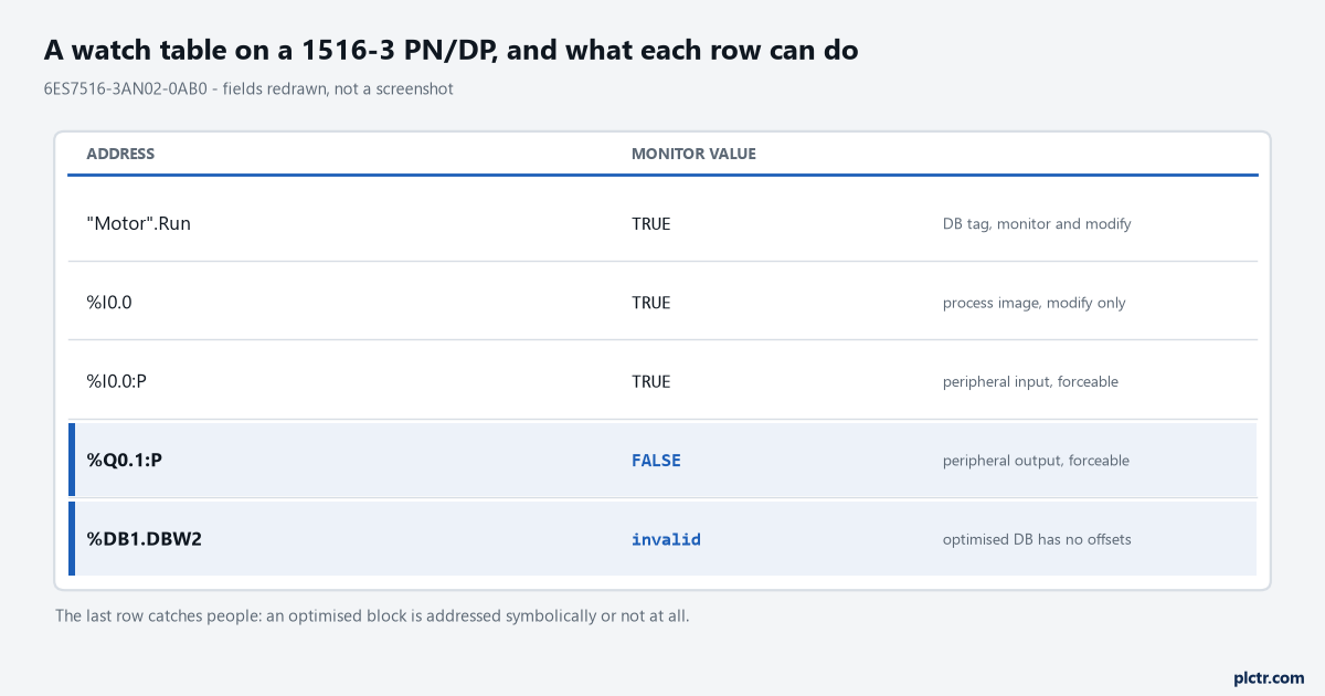
Our own drawing of the rows, not a screenshot. The last row is the one that trips people over, and the next section is why.
Modify against force, which are not the same thing at all
The fundamental difference is storage behaviour. Everything else follows from it.
Modifying is an online function. It is not stored in the CPU. You end it in the watch table or the force table, or by terminating the online connection, and that is the whole lifecycle. Forcing writes a force job to the SIMATIC memory card. The job is retained after a POWER OFF. The CPU shows an active force job with its own symbol, and on a 1516-3 PN/DP that shows on the front as RUN/STOP lit green with MAINT lit yellow. You can only end the forcing of peripheral inputs and outputs in the force table. Not by closing TIA Portal, not by power cycling, not by hoping. It survives a memory reset as well: the S7-1500 manual’s list of what a memory reset does states that data blocks lose their current values and go back to configured start values, and then, four lines down the same list, that force jobs remain active.
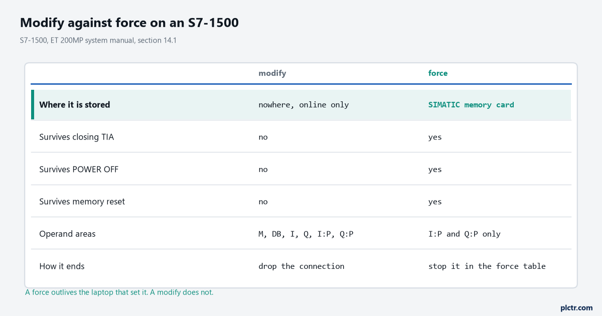
The top row is the cause and the four under it are consequences. A force is a property of the CPU; a modify is a property of your session.
The operand areas differ too.
This catches people who expect force to be the bigger hammer everywhere. On an S7-1500 the force table forces peripheral inputs and peripheral outputs, written with a :P suffix, %I0.0:P and %Q0.0:P. Forcing a peripheral input bypasses the sensor: the program receives the force value instead of the real input value, whether it reads through the process image or by direct access. Forcing a peripheral output bypasses the entire program and puts the value on the actuator.
Which is the line to stop and read again before you use it on a machine with people near it.
Why the value will not change
Now the actual question, in the order these are worth checking.
Start with the CPU being in STOP.
Automatic updates of the process image do not happen in STOP, so %I and %Q sit at whatever they were holding when it stopped. The first power-on sequence is worth knowing for this reason alone: after the flash test, where all LEDs flash at 2 Hz and RUN/STOP alternates yellow and green, the CPU runs system initialization with RUN/STOP flashing yellow at 2 Hz, then settles into STOP with RUN/STOP lit steady yellow. Steady yellow means STOP, and STOP means the numbers on your screen are stale rather than stuck. And the mode selection may be holding it there on top of that: on a 6ES7516-3AN02-0AB0 the operating mode buttons decide whether the CPU is permitted to go to RUN at all, and the manual is explicit: with STOP active you cannot switch the CPU to RUN from a communication task configured in TIA Portal or from the display. The transition table says the same thing from the other side, that STOP moves to STARTUP when the hardware configuration and program blocks are consistent and the programming device sets RUN while the mode selection is at RUN. Both conditions, not either.
Then the common one, which is not a fault at all: you modified an address that the program writes every scan.
A modify is a single write into a memory area your program owns. If the program writes that output on every pass, the program wins on the next pass, and all you saw was a flicker. The S7-1200 system manual, where this is spelled out in the most detail, describes Modify now as changing the value for one scan cycle. Force it instead, or go and find the logic that is writing it.
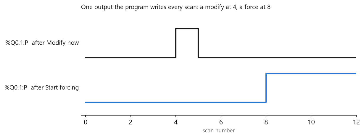
Drawn from the documented behaviour rather than captured on a rig. The two traces are the same output and the same program; only the method changed.
Then there is the absolute address typed into an optimised block. Data blocks with optimised access have no fixed structure: the elements get a symbolic name and no fixed address inside the block, arranged so the available memory is used efficiently, and the memory function manual is blunt that in those blocks you can only address tags symbolically. So "Data".FillState works and DB1.DBW2 does not exist to be watched. Standard access is the other case, where the declaration gives each element both a name and a fixed address shown in the Offset column, and both forms work. If you have inherited a project and are not sure which kind you are looking at, open the block properties rather than guessing from the address somebody else wrote.
Quietly common, and nothing to do with any of the above: an FB called from three places has three sets of values, and monitoring an address without the call path shows you one of them. Nothing is stuck. You are looking at the wrong copy.
Last, the dead end worth naming, because it is where people spend the most time and it is almost never the tool. Everybody checks the watch table setup first, then the online connection, then the block. The condition that is actually false is upstream, three networks back, in an interlock nobody mentioned when they handed the machine over. Before going further into monitoring mechanics, cross-reference the tag and find out what writes it.
And one that is not a mistake at all: you cannot read a peripheral output back from the module. The S7-1500 manual’s list of what a force table can monitor names bit memory, data block contents and peripheral inputs, and peripheral outputs are not in it. The S7-1200 manual says why in plain words, and the reason is the same on both: the monitor function can only display the last value written from Q memory, not the actual value at the physical output. If you need to know what the terminal is doing, put a meter on the terminal.
What to reach for next
Force, then stop forcing, then check the MAINT LED is out before you leave site.
A forgotten force job is the classic handover failure, and the CPU will carry it through a power cycle quite happily.
For anything that happens faster than you can watch, program status and watch tables run out very quickly, and the trace function is the tool: it records tags against configurable trigger conditions and the CPU stores the recording, which you then read back in STEP 7. That is a separate job and a separate page. When the diagnostics buffer rather than a watch table is what is telling you something, the S7-1500 area length error is a worked example of reading an entry properly. When the value you are monitoring is an analogue reading that looks wrong rather than frozen, the counts are the place to start and scaling on an S7-1500 in FBD covers what 0 and 27648 actually mean. And if the block you want to monitor will not open at all, that is not a monitoring problem: it is know-how protection, and it has its own way out.
If you are earlier in the job than this and the CPU is not talking to you yet, go back to the first download and the empty accessible-devices list.