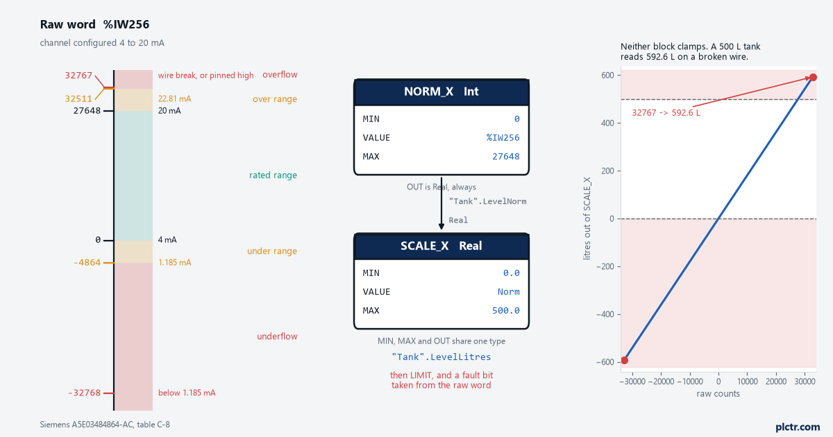
On an S7-1500 a 4 to 20 mA channel reads 0 counts at 4 mA and 27648 counts at 20 mA, and a channel with wire-break diagnostics enabled reads 32767 when the loop opens. Those three numbers decide the rest of this page: what goes in the MIN and MAX pins of NORM_X, what SCALE_X hands back, and why a tank scaled 0 to 500 litres displays 592 litres the morning somebody pulls a terminal.
The short answer, so you can go and wire it: NORM_X with MIN 0, MAX 27648 and the input word at VALUE, its Real output into SCALE_X with MIN and MAX set to your engineering range. Then clamp. The clamp is the part people leave out and it is the part that matters.
The module in the examples is an AI 8xU/I/RTD/TC ST, order number 6ES7531-7KF00-0AB0, in a 1516-3 PN/DP rack, with the project open in TIA Portal V17.
What the counts actually are
Siemens publishes one representation for all unipolar input ranges and then a per-range table in each module manual. The unipolar table, from the Analog value processing function manual A5E03461439-AC, table 3-4:
| Decimal | Measured value | Range |
|---|---|---|
| 32767 | above 117.589 % | Overflow |
| 32511 | 117.589 % | Overrange |
| 27649 | 100.004 % | Overrange |
| 27648 | 100.000 % | Rated range |
| 1 | 0.003617 % | Rated range |
| 0 | 0.000 % | Rated range |
| -1 | -0.003617 % | Underrange |
| -4864 | -17.593 % | Underrange |
| -32768 | below -17.593 % | Underflow |
Now the same ladder with real units on it. This is table C-8 of the module manual A5E03484864-AC, for a channel configured 4 mA to 20 mA against one configured 0 mA to 20 mA:
| Decimal | Hex | 0 to 20 mA | 4 to 20 mA |
|---|---|---|---|
| 32767 | 7FFF | above 23.52 mA | above 22.81 mA |
| 32511 | 7EFF | 23.52 mA | 22.81 mA |
| 27648 | 6C00 | 20 mA | 20 mA |
| 20736 | 5100 | 15 mA | 16 mA |
| 1 | 1 | 723.4 nA | 4 mA + 578.7 nA |
| 0 | 0 | 0 mA | 4 mA |
| -4864 | ED00 | -3.52 mA | 1.185 mA |
| -32768 | 8000 | below -3.52 mA | below 1.185 mA |
Read the range column before you read anything else. It changes what every count means.
The row worth staring at is 20736. On the 0 to 20 mA channel it is 15 mA. On the 4 to 20 mA channel the identical count is 16 mA. Same module, same terminal, same number in the process image, two different currents, because the range you chose in the device configuration changed what the count means.
Voltage behaves the same way. For a 0 to 10 V range the function manual gives 27648 at 10.0 V, 32511 at 11.759 V, 32767 at 11.852 V and one count as 361.7 µV. A detail that catches people specifying hardware: this particular module has no 0 to 10 V range at all. Its voltage ranges are ±10 V, ±5 V, ±2.5 V, ±1 V, ±500 mV, ±250 mV, ±80 mV, ±50 mV and 1 V to 5 V. If your transmitter is 0 to 10 V you configure ±10 V, MIN in NORM_X stays 0, and you throw away half the resolution.
Why 4 mA is not zero counts
Because the module already subtracted it.
The live-zero removal happens in hardware, once you tell it the range is 4 to 20 mA. The 16 mA span is what gets mapped to 0…27648. Nothing in your code has to know that 4 mA exists.
That is the opposite of what most people assume the first time, and the assumption produces a specific wrong answer. If you reason “20 mA is 27648, so 4 mA must be a fifth of that, so 5530” and put 5530 into NORM_X as MIN, a correctly configured channel now reads low at the bottom and the error shrinks as you climb. Full scale is right, zero is not, and that is the signature. The same number, 5530, happens to be the correct MIN in exactly one situation: the channel is configured 0 mA to 20 mA and a 4 to 20 mA transmitter is wired into it. Then 4 mA really does land on 0.2 × 27648 = 5529.6, so 5530, and the module is not subtracting anything, because you never told it there was anything to subtract. Which means the answer to “should MIN be 0 or 5530” is not a matter of opinion and never was. Open the device configuration and read which range the channel is set to. It settles the argument in four seconds and it is the only thing that settles it.
Two-wire transmitters narrow it further, and if you are still deciding how to wire one, the wiring side of analogue and digital I/O is a separate job from the scaling. On this module the 2WMT measurement type offers 4 mA to 20 mA and nothing else, because the transmitter is drawing its supply through the same pair and cannot go to zero and stay alive.
NORM_X and SCALE_X, and what each one is allowed to be
The two instructions are defined in the S7-1200 system manual A5E02486680-AP, section 8.7.5, in the same wording that applies on the S7-1500:
NORM_X:   OUT = (VALUE - MIN) / (MAX - MIN)
SCALE_X:  OUT = VALUE (MAX - MIN) + MIN
The data types are the part that decides whether your network compiles and whether it is right.
| Pin | NORM_X | SCALE_X |
|---|---|---|
| MIN | SInt, Int, DInt, USInt, UInt, UDInt, Real, LReal | same list |
| VALUE | same list | Real, LReal only |
| MAX | same list | same list |
| OUT | Real, LReal only | SInt, Int, DInt, USInt, UInt, UDInt, Real, LReal |
Two rules come with that. For NORM_X, MIN, VALUE and MAX must all be the same data type. For SCALE_X, MIN, MAX and OUT must all be the same data type. So an Int input word, Int constants 0 and 27648, a Real intermediate, then Real constants on SCALE_X and a Real output. The ??? on the block in FBD is you choosing that type, and clicking past it accepting whatever TIA guessed is how half the odd results happen.
In FBD the network is two blocks and one intermediate tag:
%IW256  ──► NORM_X ──► "Tank".LevelNorm ──► SCALE_X ──► "Tank".LevelLitres
   MIN 0        Int          Real              MIN 0.0        Real
   MAX 27648                                   MAX 500.0
Give the intermediate a real name in a DB. A Real in bit memory called MD300 with no comment is the tag that nobody can find in two years.
Where the Int quietly eats your resolution
Set OUT on SCALE_X to Int and the fraction is gone. That is not a bug and the block will not warn you, because the manual’s ENO table says ENO goes to 0 only when the result exceeds the valid range of the OUT data type, not when it loses precision getting there. For a 0 to 500 litre tank into an Int you have given up nothing you had, since a litre is finer than the tank is worth measuring anyway and the transmitter is not that good. For a pressure transmitter ranged 0 to 10.00 bar scaled into an Int you have just built a 1 bar resolution instrument out of a module that resolves 0.000362 bar, and the trend on the HMI will show a staircase that somebody will eventually blame on the transmitter. Scale into a Real. If the HMI wants an integer, do the multiply-by-100 and the conversion at the HMI end where it is visible and where the next person can see what you did.
One more thing the manual is explicit about and people rely on anyway: if VALUE into SCALE_X falls outside 0.0 to 1.0, the block still runs and still sets ENO true, and just gives you a number outside MIN and MAX. ENO is not a range check.
Above range, below range, and the 32767
Neither block has any idea what a valid reading is. They do arithmetic on whatever arrives.
Feed 32767 into NORM_X with MIN 0 and MAX 27648 and the arithmetic is obedient: 32767 / 27648 = 1.18514. SCALE_X then returns 1.18514 × 500 = 592.6 litres on a 500 litre tank. Nothing faults. The overfill interlock, if it is looking at litres, trips. The operator sees a number that is plainly impossible and concludes the PLC is broken.
Underflow does the mirror image. -32768 / 27648 = -1.18519, which on the same tank is -592.6 litres.
So the network needs three more things after SCALE_X, and they are not optional:
- a comparison on the raw word, before scaling, that sets a
Faultbit when the raw word reaches 32511 or falls to -4864 - a LIMIT on the scaled value, clamped to the engineering range
- a decision about what the rest of the program does with the fault bit, which is usually hold last good value and alarm, not freeze at zero
Reading the raw word rather than the scaled value is the point. 32511 and -4864 are boundaries with meaning; 592.6 litres is a number you would have to reverse-engineer.
If the channel’s value status is mapped into the process image you get this for free per channel, and it is worth the address space.
The broken wire
This is the one channel setting that is worth arguing about in a design review.
Enable wire-break diagnostics on the channel and set the threshold. On this module the current limit is selectable between 1.185 mA and 3.6 mA. Pick 3.6 mA for a 4 to 20 mA transmitter: it catches a loop that has gone open or a transmitter that has died, well before the reading drops into the underrange.
What appears in the process image depends on which diagnostics you enabled. Table C-21 of the module manual:
| Configuration | Measured value |
|---|---|
| Wire break enabled, overflow/underflow either way | 32767 (7FFF) |
| Wire break disabled, overflow/underflow enabled | -32767 (8000 H), plus a “low limit violated” alarm |
| Both disabled | -32767 (8000 H) |
Wire break takes priority over overflow and underflow when both are enabled. And note that the manual prints the value as -32767 with hex 8000, while 8000 hex is -32768. Do not test for equality with -32767 in your comparison. Test for -32767 or lower, and the code is right whichever the firmware actually puts there. A loop that reads exactly 32767 and a loop that is genuinely pinned above 22.81 mA look identical in the process image, which is the limit of what you can learn by testing for magic numbers, and the reason to spend the configuration time instead. The diagnostics buffer and the channel value status tell those two cases apart. That is what they are for.
The same network in SCL
Three lines, and easier to read than the FBD in most cases:
"Tank".LevelLitres := SCALE_X(MIN := 0.0,
                              VALUE := NORM_X(MIN := 0, VALUE := "Tank".Raw, MAX := 27648),
                              MAX := 500.0);
Same instructions, same types, same need for a clamp. If your standard is FBD for I/O handling and SCL for everything else, this is a fair place to break the rule and put the whole conversion in one SCL FC that takes the raw word and the two limits and hands back a Real plus a quality bit. Eight channels then cost eight calls instead of sixteen blocks and eight intermediate tags.
What replaced SCALE and UNSCALE, and why
If you have moved code off an S7-300, you know SCALE and UNSCALE from the standard library: an Int in, a BIPOLAR flag, a RET_VAL error code, a Real out. They still exist. Siemens’ own comparison list A5E33285102-AH marks both of them Legacy, with the recommendation reading “Symbolic programming”. The practical difference is the BIPOLAR pin, a boolean that silently reinterprets the whole input range, and getting it wrong gives a result that is exactly half right across the top of the range and wrong everywhere below the midpoint. NORM_X has no such pin. You write the actual limits, 0 and 27648 or -27648 and 27648, and the block does what the numbers say, which means a person reading the network six months later can see the range without opening the help. That is the whole argument for the change, and it is a good one.
Next
Open the device configuration, read the measuring range on the channel you are about to scale, and write it in the network comment. Then force the transmitter to 4 mA and to 20 mA with a loop calibrator and confirm you get 0 and 27648 before you trust any engineering unit on the screen. If the ends are right the middle is right, because the module is linear and the block is arithmetic.
If you are writing this in STL instead, the arithmetic is yours to get right and the failure is quieter. That is covered separately in scaling an analogue input in STL.