A DINT stops at 2147483647, and 27648 multiplied by 77673 is 2147503104. That is the whole of the problem with fixed-point scaling in STL: the arithmetic is exact right up to the statement where it is not, and *D reports the crossing by setting OV and OS rather than by refusing to run.
Here is the chain that works, for a transmitter ranged -50.0 to +150.0 °C on a 4 to 20 mA channel, holding the result in tenths of a degree:
      L     PIW  256      // raw counts, 0 at 4 mA, 27648 at 20 mA
      ITD                 // 16-bit Int to 32-bit DInt, sign extended
      L     L#2000        // span, in tenths: 200.0 degC
      *D                  // 0 ... 55 296 000, well inside a DINT
      L     L#27648
      /D                  // quotient only, remainder discarded
      L     L#-500        // offset, -50.0 degC in tenths
      +D
      T     MD   20       // result in tenths of a degree
Raw 27648 gives 2000, minus 500, so 1500, which is 150.0 °C. Raw 0 gives -500, which is -50.0 °C.
Multiply first, and it is not a style preference
/D is documented plainly: “The result gives only the quotient and not the remainder.” No rounding, no fraction, nothing kept.
Divide before you multiply and the chain becomes this:
      L     PIW  256
      ITD
      L     L#27648
      /D                  // <-- zero for every raw value below 27648
      L     L#2000
      *D
Every reading in the working range returns 0 until the transmitter reaches exactly full scale, at which point the display snaps to 200.0. Somebody will call that a faulty analogue card. It is two statements in the wrong order.
The same hazard hides in subtler forms. Any intermediate division truncates, and once digits are gone no later multiply brings them back. Keep every division at the end of the chain, and if you need two of them, do the multiplies first and combine the divisors into one. Scale factor choice matters for the same reason. Working in tenths of a degree, the quotient is truncated to 0.1 °C. The module resolves 200 °C over 27648 counts, which is 0.0072 °C per count, so you have thrown away a factor of fourteen. Hundredths (L#20000) costs nothing here and gets it back.
Where it overflows, exactly
The ceiling is not where the datasheet suggests it is, and the difference matters.
The DINT range in the STL reference manual A5E41492943-AA is -2147483648 to 2147483647, and the *D status table is precise about what happens at the edges:
| Result | CC 1 | CC 0 | OV | OS |
|---|---|---|---|---|
| Product = 0 | 0 | 0 | 0 | – |
| Product negative, down to -2147483648 | 0 | 1 | 0 | – |
| Product positive, up to 2147483647 | 1 | 0 | 0 | – |
| Product above 2147483647 | 1 | 0 | 1 | 1 |
| Product below -2147483648 | 0 | 1 | 1 | 1 |
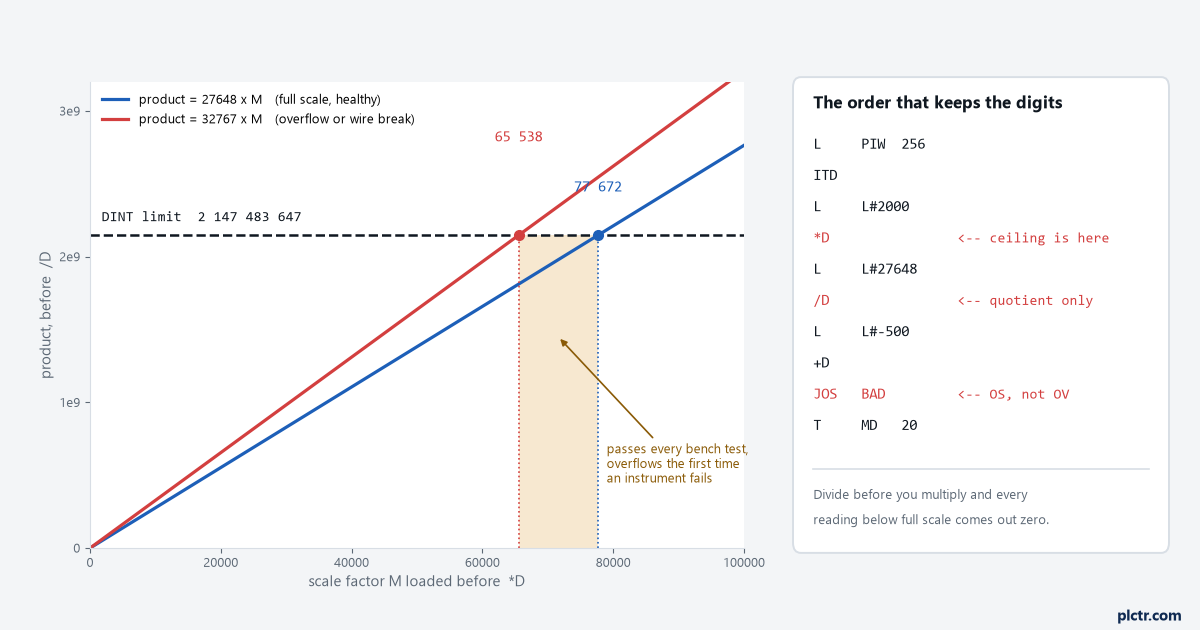
So the ceiling on your span constant, with the raw value at full scale, is 2147483647 / 27648. That works out to 77672: 27648 × 77672 = 2147475456, which fits. 27648 × 77673 = 2147503104, which does not. That is the number to write in your head. Any scale factor at or above 77673 overflows on a healthy full-scale reading. But 27648 is not the largest value the process image can hand you. An overflow reading is 32767, and so is a broken wire on a channel with wire-break diagnostics enabled. Redo the division against 32767 and the ceiling drops sharply: 32767 × 65538 = 2147483646, which fits, and 32767 × 65539 = 2147516413, which does not. Your real safe ceiling is 65538, not 77672. The gap between those two numbers is where the interesting bugs live, because code written against 27648 passes every bench test and then overflows the first time an instrument fails.
Working in hundredths of a degree over a 200 °C span means a factor of 20000, comfortably clear of both. Working in thousandths of a bar over a 400 bar span means 400000, and that overflows on a good reading, never mind a bad one.
What value you actually get
Honestly, nobody publishes this, and that is itself the answer.
The manual defines the status bits. It does not define what is left in ACCU 1 after *D overflows, and I am not going to invent a number for it. The text says only that when OV and OS are set “the result is outside the range of a 32-bit integer number”. Treat that as: the value is meaningless, and any logic reading MD20 downstream is reading rubbish that looks like a number. Test the status bits, or size the constants so it cannot happen, and preferably both. /D has one overflow case of its own and it is worth knowing because it surprises people who assume division cannot overflow. From the same status table: quotient = 2147483648 sets OV and OS. That is -2147483648 divided by -1, the one division whose answer does not fit. Division by zero sets CC 1, CC 0, OV and OS all to 1.
Check OS, not OV, and use JOS
This is the part that gets skipped, and the STL reference manual makes the point itself in the JOS example.
Both bits exist because one of them is useless to you here.
OV reflects the instruction that just executed. Run *D, then /D, then +D, and by the time you look at OV it is telling you about +D alone. An overflow in the multiply two statements earlier has already been overwritten.
OS is the stored version. It latches when any of the arithmetic sets OV and stays latched until you read it.
      L     PIW  256
      ITD
      L     L#2000
      *D
      L     L#27648
      /D
      L     L#-500
      +D
      JOS   BAD           // taken if OS = 1 anywhere in the chain above
      T     MD   20
      ...
BAD:  S     M    10.0     // scaling fault, hold last good value
The manual’s own note on this is worth quoting because it is the mistake it expects you to make: “In this case do not use the JO instruction. The JO instruction would only check the previous -I instruction if an overflow occurred.”
JOS clears OS when it executes, so the check arms itself again for the next scan. Put it once, after the last arithmetic statement, not after every one.
ITD, DTR and the accuracy you lose in the conversion
Two conversions bracket the arithmetic, and only one of them can lose you anything.
ITD
*I on 16-bit values overflows at 32767 and your very first multiply is already past that.DTR converts the DINT to a 32-bit IEEE float. The manual’s wording is the interesting bit: “If necessary, the instruction rounds the result. (A 32-bit integer has a higher accuracy than a 32-bit floating point number.)” That is not a typo. The bit layout in the same manual shows one sign bit, an 8-bit exponent and a 23-bit mantissa, so a Real holds every integer exactly only up to 16777216. Above that, DTR rounds and the value you get back is not the value you put in. A millisecond runtime counter at 40 days is past it. A scaled temperature in tenths is nowhere near it. Going the other way, the four rounding instructions differ and the manual spells out how. TRUNC rounds toward zero. RND+ rounds toward plus infinity and RND- toward minus infinity. RND rounds to nearest and, on a tie, to the even result: the manual’s examples give 100.5 becoming +100 and -100.5 becoming -100. If you have been assuming RND rounds halves up, it does not.
All four set OV and OS when the source cannot be represented as a 32-bit integer, and none of them performs the conversion in that case.
Moving the block, and the ACCUs underneath it
Here is the one that gets people when the same FC is copied from an S7-400 to an S7-300 or the other way.
The answer is not in the instruction set. It is in the hardware underneath it.
The integer maths instructions in the S7-300 and S7-400 instruction set all carry the same sentence in the manual: the contents of accumulator 2 remain unchanged on CPUs with two accumulators, while on CPUs with four accumulators the contents of accumulator 3 are copied into accumulator 2 and accumulator 4 into accumulator 3. A straight L, L, *D, L, /D chain does not care, because it never leaves anything parked in ACCU 3. Code written by somebody who did know about four accumulators, and who used ACCU 3 as scratch space between operations, cares a great deal. It works on the S7-400 it was written for and quietly computes something else on an S7-300. If you are inheriting STL of unknown provenance, this is the thing to look for before you look at anything else: a load sequence that pushes more than two values before the first arithmetic statement.
STL itself travels further than people expect. Siemens’ comparison list A5E33285102-AH shows the STL column covering S7-300, S7-400 and S7-1500, with a footnote that some instructions have to be called via CALL, and states that the S7-1200 supports only LAD, FBD and SCL. So an STL block moves to an S7-1500, where you would open it in TIA Portal like anything else. It does not move to an S7-1200, and that decision is made at the quote stage, not at commissioning. On the S7-1500 you would normally not write this at all. NORM_X and SCALE_X do it in two blocks with the Real maths handled for you, which is the FBD answer to the same question. The reason to keep the STL version is that it is already running on four hundred machines and the maintenance team can read it.
The raw values the chain has to survive
None of this arithmetic is safe until you know what can arrive at the front of it.
Whatever you write, it will be handed these, and they come from the module and its wiring rather than from anything in your code. From the unipolar representation in the Analog value processing manual A5E03461439-AC and table C-8 of the module manual A5E03484864-AC, for a 4 to 20 mA channel:
| Decimal | 4 to 20 mA | Range |
|---|---|---|
| 32767 | above 22.81 mA | Overflow, or wire break |
| 32511 | 22.81 mA | Overrange |
| 27648 | 20 mA | Rated range |
| 0 | 4 mA | Rated range |
| -4864 | 1.185 mA | Underrange |
| -32768 | below 1.185 mA | Underflow |
Two comparisons on the raw word before the arithmetic starts cost less than any recovery from an overflow:
      L     PIW  256
      L     32511
      >=I
      JC    BAD
      L     PIW  256
      L     -4864
      <=I
      JC    BAD
The reason to test the raw word rather than the scaled result is that 32511 and -4864 are boundaries Siemens defined and published. A number in tenths of a degree is a boundary you would have to work backwards to find, and it changes every time somebody re-ranges the transmitter.
Next
Take the scaling FC you already have and do one piece of arithmetic on it: multiply 32767 by your largest scale constant and see whether the answer clears 2147483647. If it does not, add the JOS and move on. If it does, the fix is usually to work in larger engineering units rather than to restructure the maths.
Then check what the raw counts mean on the channel that feeds it, because the arithmetic being right does not help if 0 counts is not the value you think it is. The counts, the ranges and the wire-break behaviour are in the FBD article, and they apply identically here.