RSLogix 500 PLC Programming PID Control Example
PLC Programming PID Control
In the previous article, we gave information about what is PID and PID control. Now we will learn how to control the pressure with PID in PLC.
In the following program example, the PID instruction is used to control the pressure of a vessel using a pressure transmitter as the process variable and a flow valve as the control variable. The setpoint is maintained at 50 psi.
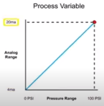
The pressure transmitter identified as the process variable converts 0 to 100 PSI to a 4 to 20 milliampere signal with a linear relationship 0(zero) psi measured at the transmitter produces a 4 milliampere signal and at 100 PSI a 20 milliampere signal is produced.
Transmitter: It is a device that outputs the measured pressure unit in amperes and voltages. Generally, the ones with milliamp output are preferred.
The Analog input module converts the 4 to 20 milliamp signal to a digital value ranging from 3277 to 16380 for a 4 milliamp signal results in a value of 3277 and a 20 milliamp signal results in a value of 16384.
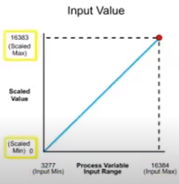
The input value is scale to a range of 0 to 16383 compatible with the PID instruction using the scale with parameters instruct for SCP.
The input parameter of the SCP instruction contains the memory address of the analog input module.
The input minimum and input maximum our program as the smallest and largest value is produced by the analog input module
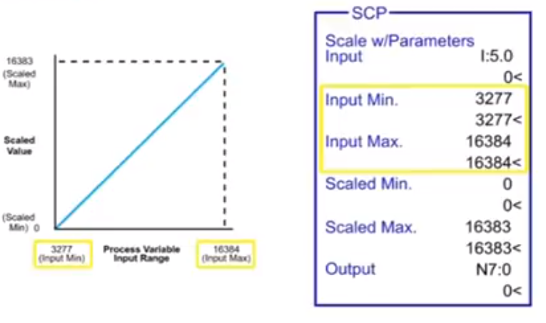
The input values are then scaled between the ranges programmed in scaled minimum and scaled maximum parameters, scale minimum value is programmed is 0 representing the low end of the output range. Scale maximum value is programmed as 16383 representing the high end of the output range. The SCP output parameter is the integer file address where the scaled output is stored and then used by the PID instruction as the process variable.
For example, when the minimum pressure of 0 psi is measured a scale value of zero is transferred to the SCP output, and when 100 PSI has measured a scale value of 16383 is transferred to the SCP output.
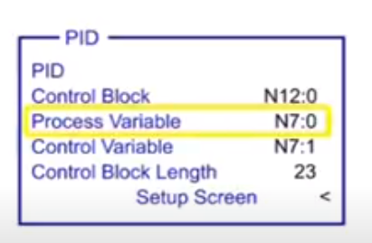
In the PID instruction the process variable parameter is programmed as an integer file which is the scale value from the SCP instruction. The control variable parameter is programmed as an integer which is the memory address for the output value.
Next, the control variable range of 0 to 16383 is scaled to an analog output module using the second scale with parameter instruction. the input parameter of the SCP contains the memory address of the PID output values that will be scaled.
The input minimum and input maximum are programmed as the smallest and largest values of the input range.
The input value is then scaled between the ranges programmed in scaled minimum and scaled maximum parameters scale minimum value is programmed at 6242 representing the low end of the analog output module range. Scale maximum value is programmed as 31208 representing the high end of the analog output module range.
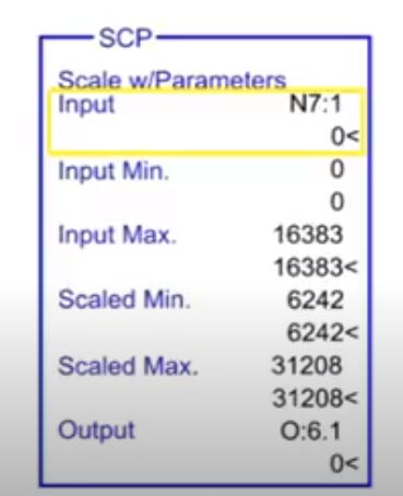
The SCP output parameter is the file address of the analog output module. The analog output module converts the digital value in the range of 6242 to 30 1208 to an analog signal of 4 to 20 milliamps.
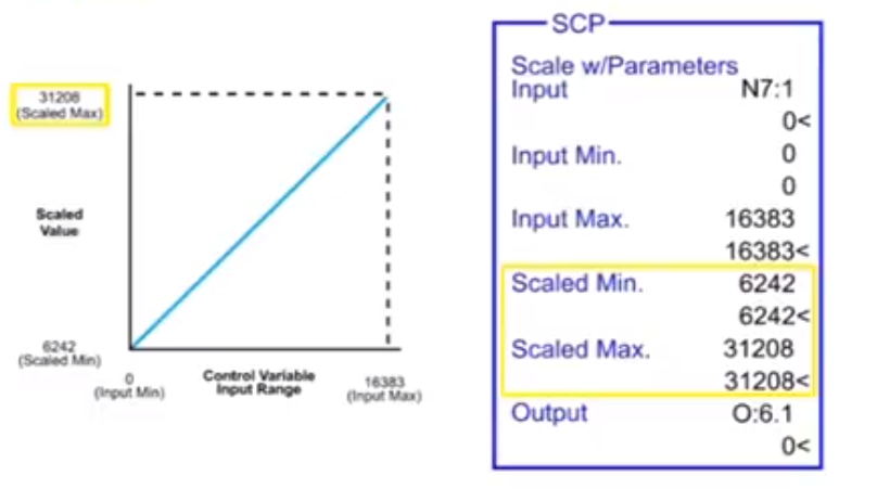
The analog signal is then sent to the flow valve where the operating range is adjusted between 0 and 100%. With the data scaled using the SCP instruction the process of controlling the pressure of the vessel 250 psi continues by entering the set point of 50 in the PID setup menu.
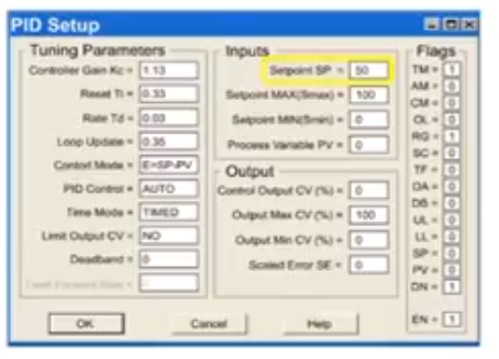
Has the PID instruction is executed a scaled error is generated by subtracting the process variable from the setpoint. By increasing the control output the error is reduced to attain the setpoint as the PSI is raised in the system.
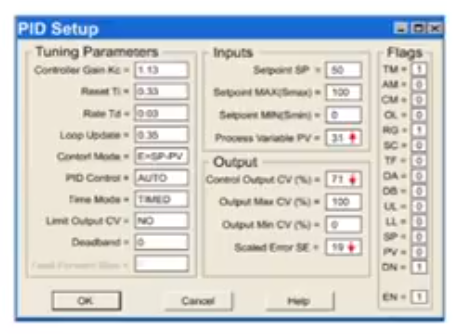
In other words the valve position is gradually closed to reduce the pressure loss.
Upon reaching the set point in the system the control output and scaled error is reduced to zero.