Fourteen stations, a 62 second takt, and a line that loses eleven minutes a shift that nobody can account for. That is the normal starting point. PLC automotive manufacturing work is less about clever logic than about structure: the same state machine at every station, error proofing that cannot be talked around, and downtime data that names the station actually at fault instead of the one that stopped first. This walkthrough covers all three on a trim and final line built from CompactLogix stations under a ControlLogix line controller.
The line
| Item | This example |
|---|---|
| Line controller | 1756-L83E ControlLogix 5580, Studio 5000 v33, one per line segment |
| Station controllers | 5069-L320ER CompactLogix 5380, one per station |
| Between them | Produced and consumed tags over EtherNet/IP, one UDT each way per station |
| Takt | 62 s, 420 bodies per shift |
| Fastening | Atlas Copco Power Focus 6000, PROFINET for the interlock, Open Protocol for the trace |
| Identification | Fixed barcode reader on the skid, VIN into the line controller |
Produced and consumed tags rather than messaging. A MSG per station per cycle turns into a queue you have to manage, and the consumed tag gives you a connection status bit for free.
Step 1: Split the work between station and line
The station PLC knows about clamps, tools, sensors and the operator. The line PLC knows about the sequence of bodies, the identity on each skid, the andon state and the counters. Drawing that line early stops the two from fighting.
Practical split that has held up for me:
- Station owns: all field I/O, its own state machine, its interlocks, its alarms, its cycle timer.
- Line owns: skid tracking, VIN to station assignment, release permission, the andon board, downtime reasons and production counts.
- Crossing the boundary: a fixed UDT each way. Station sends state, cycle time, quality result and alarm word. Line sends part data, release permission and mode.
- Nobody reaches across. The line PLC never writes a station’s output. If it needs something to move, it asks the station.
Keep the UDT the same for every station even when a station does not use half of it. Identical interfaces mean the line code is one loop over an array, and a new station is a copy of an existing one.
Step 2: Give every station the same state machine
Use the OMAC PackML model. Not because of the badge, but because the words Held and Suspended already mean something specific, and that distinction is where your downtime data comes from. Held is an internal problem, the station’s own fault. Suspended is external, starved by upstream or blocked by downstream.
The states you will actually use: Idle 4, Starting 3, Execute 6, Completing 16, Complete 17, Holding 10, Held 11, Unholding 12, Suspending 13, Suspended 5, Resetting 15, Stopped 2, Aborted 9.
(* StationTask, 20 ms periodic, routine State, Structured Text *)
CASE State OF

  4:  (* Idle: reset done, waiting for a body and a release *)
      Stn.CycleTime := 0;
      IF Body_Present AND Line.ReleaseToWork AND NOT Alarm_Any THEN
          State := 3;                      (* Starting *)
      END_IF;

  3:  IF Clamps_Closed AND Tool_Ready THEN
          Cyc_Start := WallClock_ms;
          State := 6;                      (* Execute *)
      END_IF;

  6:  Stn.CycleTime := WallClock_ms - Cyc_Start;
      IF Alarm_Any OR EStop_Reset_Req THEN
          State := 10;                     (* Holding, our own fault *)
      ELSIF NOT Upstream_Has_Body OR Downstream_Blocked THEN
          State := 13;                     (* Suspending, someone else's fault *)
      ELSIF Batch_OK AND Vision_OK THEN
          State := 16;                     (* Completing *)
      END_IF;

 16:  IF Clamps_Open AND Body_Clear THEN
          Good_Count := Good_Count + 1;
          Over_Takt := (Stn.CycleTime > TAKT_MS);
          State := 4;
      END_IF;

 10:  Hold_Reason := First_Out_Code;        (* captured once, see step 5 *)
      State := 11;                          (* Held, waiting for the operator *)

 11:  IF Reset_PB AND NOT Alarm_Any THEN
          State := 12;                      (* Unholding *)
      END_IF;

END_CASE;

Stn.StateCurrent := State;                  (* to the line PLC, every scan *)
Two things that matter more than the state numbers. Write the cycle time from a wall clock, not by counting scans, because a station that overruns is exactly when the scan gets long. And publish StateCurrent every scan rather than on change, so the line PLC never has to guess after a comms blip.
If a station has a long fixed sequence rather than a single work step, drive the same states from a sequencer. The mechanics are in PLC sequencer programming and the structured version in implementing sequential function charts in PLC programming.
Step 3: Error proof the fastening so it cannot be argued with
A torque tool on a fieldbus is the most useful poka-yoke in the plant, and the most commonly defeated.
- The PLC selects the Pset or job number for the model on the skid. The operator never picks it on the controller keypad.
- The tool returns OK, NOK and a batch complete signal after the programmed number of bolts.
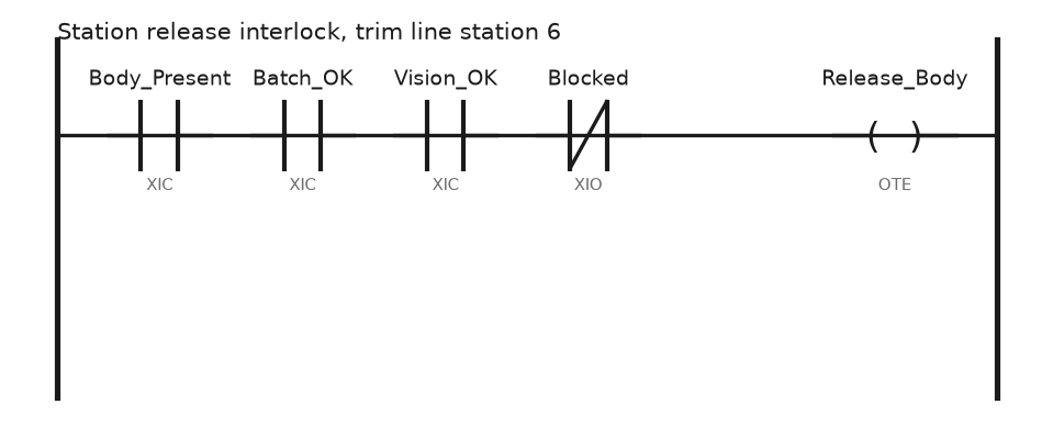
- The station will not release the body until batch complete is true for every tool in the station.
- A NOK requires a loosening sequence and a retry that is counted. Three retries raises the andon rather than silently passing.
- Torque and angle traces go to the tool server over Open Protocol on the Ethernet side. Do not try to log curves in the PLC; log the result bit and the timestamp, and let the tool controller keep the curve against the VIN.
Add the sockets to that. A photo-eye or an RFID tag per socket in the tray tells the PLC which socket the operator picked up. Identification of the body itself, by barcode or tag, is the other half; implementing RFID technology with PLC systems covers the reader side.
Step 4: Measure the cycle where the takt lives
Cycle time per station means the time in Execute, from first motion to release, on the same clock for every station. Keep three numbers per station and per shift:
| Number | How | Why |
|---|---|---|
| Average cycle | Sum of Execute time over good count | Tells you the station’s normal |
| Over-takt count | Increment when cycle exceeds takt | The honest measure of a bottleneck |
| Worst cycle and its VIN | Store max plus the identity | Gives quality something to look at |
The average hides everything. A station averaging 54 seconds against a 62 second takt still stops the line if eleven bodies a shift take 80. Chase the over-takt count.
Step 5: Make downtime blame the right station
Two rules, and most downtime reporting is fixed.
First out. When a station goes to Held, capture the alarm that caused it once, in the same scan, and latch it. If you evaluate all alarm bits every scan the cascade wins and every event reads “E-stop” or “safety circuit open”. Capture the first true bit, freeze it until the reset, and log the alarm word alongside for context. The fault routine pattern in create controller fault routine uses the same idea at the controller level.
Held against Suspended. A station that stops because the one downstream is full is not broken. If you record that as station downtime, maintenance spends a week on a station with no fault. Suspended time gets allocated to the cause, which the line PLC knows because it knows who is blocked and who is starved.
For the andon itself, a yellow call means the operator needs help inside this cycle and a red means the line stops. A fixed position stop, where the line finishes the current cycle before stopping, keeps work from being left half done on a body. Wire the pull cord to the line controller, not the station, because it is a line decision.
Field notes
The bolt counter that reset at shift change. Batch counts were cleared at 06:00 with the shift counters. A body that went into break half fastened came out counted as complete, and the audit found it three weeks later. Batch data belongs with the body, in the skid record, not in a shift counter. We moved it into the tracking array indexed by skid.
First out that was last out. The first-out logic scanned the alarm array from index 0 upward every scan, so it always reported the lowest numbered alarm. Since the E-stop word sat at index 0 and every station fault drops the E-stop relay chain, all fourteen stations reported E-stop for six months. Latch on the rising edge, not on the scan.
Two skids, one VIN. The barcode reader on station 4 read through a gap and picked up the next skid’s label during index. The line assigned torque data to the wrong body. Gate the read with a skid-in-position sensor, and reject any read that arrives while the conveyor is moving.
Produced tag RPI set to 5 ms for all fourteen stations. Someone wanted responsive data. The line controller’s CPU utilisation went past 80 percent and the HMI began to lag. Body tracking does not need 5 ms. We set the produced tags to 50 ms, utilisation dropped under 40, and nothing about the line behaved differently.
Frequently asked questions
Is PackML worth it on a line that is not packaging?
Yes, for the state names and the Held against Suspended split. You can ignore the modes and the full PackTags structure. What you want is every station describing itself with the same vocabulary.
Where should the production count live?
In the line controller, incremented on the release of the last station, and pushed to MES. Counting at each station gives you fourteen numbers that never agree. Integrating PLC with MES covers the handoff.
How do I track a body through the line?
An array indexed by skid or position, shifted on index, holding VIN, model, quality results and timestamps. Rebuild it from the readers on restart rather than trusting retained data after a long stop.
Should the safety circuit stop the whole line or just the station?
Zone it. A station guard opens that station and everything whose motion can reach into it. Stopping a whole line for one guard door costs more than it protects, and operators will defeat it.
What is a realistic micro-stop figure to aim at?
Measure before you set a target. On most lines stops under 60 seconds outnumber the long ones ten to one and add up to more lost time, and nobody logs them by hand. That is the case for logging them in the PLC.
Next step
Once stations report state, cycle and first-out alarms in the same format, the useful next move is watching the equipment rather than the product: drive current, clamp cylinder travel times, tool service counts. Start at PLC condition monitoring and predictive maintenance. For the robot stations on the same line, PLC robot integration has the handshake pattern.