Learning the PLC hardware components one at a time is easy. The part people get wrong is the join: which piece of software owns which piece of hardware, and what happens to your logic when one of them is swapped. This walks through a rack from the power supply to the terminal block, then through the project structure that addresses it, using a ControlLogix and an S7-1500 side by side.
Catalogue numbers below are for a small system of each type, the kind that runs one machine with about 60 discrete points and a handful of analogs.
What is physically in the enclosure
| Part | Job | Fails as |
|---|---|---|
| Chassis or rail | Carries the backplane that modules talk over | Bent pins, a module that will not seat |
| Power supply | Feeds the backplane rails, not the field devices | Everything dead, or random module faults under load |
| CPU or controller | Runs the tasks, holds the project and the firmware | Major fault, or a controller stuck in program mode |
| Discrete I/O | 24V DC or 120V AC inputs, transistor or relay outputs | A blown output group, a channel stuck on |
| Analog I/O | 4 to 20 mA, 0 to 10V, RTD and thermocouple | Drift, a floating input reading garbage |
| Comms modules | EtherNet/IP, PROFINET, serial, DeviceNet | Lost connection, a red module status LED |
| Terminal blocks and wiring arm | Field wiring, and the reason a card can be swapped in two minutes | Loose ferrule, one terminal torqued by nobody |
Field power is separate from backplane power. A 1756-PA72 feeds the backplane from 120 or 240 VAC. It does not feed your sensors. The 24V supply for field devices is a separate DIN rail unit, sized for the sensors, valves and the output cards that switch them.
Size the power supply before you fill the rack
Every module draws current from the backplane, and Studio 5000 will happily let you configure a rack the physical supply cannot carry. Add up the milliamp figures from each module data sheet for each backplane rail, then compare with the supply rating. Leave headroom for the module somebody adds next year.
Two symptoms of an overloaded supply: modules that fault at random with no pattern, and a rack that behaves perfectly until the outputs are energised. Both are commonly diagnosed as a bad CPU first.
The CPU: memory, firmware and project
Controller memory comes in two flavours that people mix up.
- User memory holds the project: logic, tags, and the data. A 1756-L83E has 10 MB of it. A CPU 1511-1 PN has a much smaller work memory split between code and data, with the load memory on the SIMATIC memory card.
- Non-volatile storage is the copy that survives a power cycle. On a ControlLogix 5580 it is the SD card, with the store and load behaviour set in Controller Properties. On an S7-1500 the project lives on the memory card by design, so the CPU is genuinely empty without it.
Retentive data works differently between the two and it catches people moving across.
| Question | ControlLogix | S7-1500 |
|---|---|---|
| What survives a power cycle | All tag values, held in controller memory | Only what you mark retentive |
| Where you set it | Nothing to set for tags, use the SD card image for the program | Retain checkbox on DB tags, retain range for M and timers |
| What clears it | A download, or a memory card load | A download of a changed block, or MRES |
Firmware is not the project. The controller firmware major revision must match the project major revision before a download will take. Flashing is a separate job with ControlFLASH Plus, and it is not something to start during a shift. The procedure is covered in PLC controller firmware upgrade.
I/O modules and how the program sees them
A discrete input card converts field voltage into a bit in the input image. What matters when you pick one:
- Voltage and polarity. 1756-IB16 is 24V DC sinking, which expects sourcing sensors. Get this backwards and nothing works, with no fault light to help you.
- Point count and grouping. A 16 point card with one common is cheaper than two isolated groups, and useless when you need two separate 24V zones.
- Output type. 1756-OB16E is an electronically protected transistor output for 24V DC loads. 1756-OW16I gives you isolated relay contacts for mixed voltages and slow loads.
- Diagnostics. Diagnostic cards report open wire and blown fuse per point. They cost more and they pay for themselves the first time an electrician does not have to ring out a loom.
- Analog resolution and update. A 1756-IF8 sampling every 20 ms is not the right card for a pressure loop that needs 5 ms. Analog card update time is separate from RPI, and both sit in front of your PID.
Physical wiring detail, sinking and sourcing diagrams and analog scaling are in the basics of input and output modules.
There is one scan of delay hiding between the field and your logic, and it surprises people debugging fast machines.
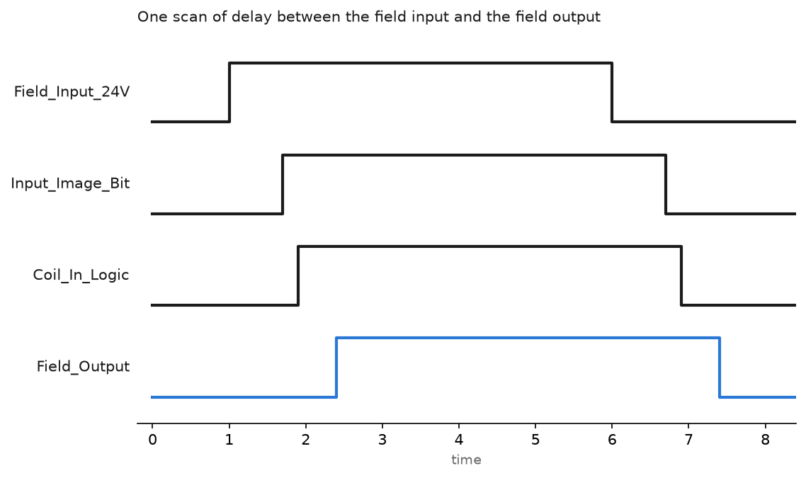
The input filter on the card adds to that. Default filter times of 1 ms to 8 ms are normal on DC input cards and are configurable per group. On a machine counting parts at 40 per second, the filter setting is the difference between an accurate count and a miscount nobody can explain.
The software side: tasks, programs and routines
A Logix project is a tree, and the tree decides execution order.
Controller Line3_Filler
|- Tasks
|  |- MainTask            continuous
|  |  |- MainProgram
|  |     |- MainRoutine       JSR to everything below
|  |     |- Conveyor          start/stop, jam detect
|  |     |- Filler_Seq        the sequence
|  |- FastTask            periodic, 10 ms, priority 5
|     |- Weigh
|        |- Scale_Read        reads the load cell card
|- Motion Groups
|- Add-On Instructions
|- Data Types
|- I/O Configuration
   |- 1756 Backplane
      |- 1756-IB16   Local_DI_Slot2
      |- 1756-OB16E  Local_DO_Slot3
MainTask runs continuously, which means it restarts as soon as it finishes. A periodic task interrupts it at a fixed rate. Priority decides who wins when both are ready. Put the fast, small work in a periodic task and leave the bulk in the continuous one.
Siemens uses the same idea with different names. OB1 is the cyclic organisation block, OB30 to OB38 are cyclic interrupts with a set period, and FB and FC blocks hold the code. A function block gets an instance data block, which is why the same FB can run twelve conveyors with twelve separate sets of memory.
Tags against addresses
| Concept | Logix | S7-1500 |
|---|---|---|
| Field input bit | Local:2:I.Data.0, usually aliased | %I0.0, with a symbolic name in the PLC tag table |
| Readable name | Alias tag Conv1_Jam_PE | PLC tag Conv1_Jam_PE mapped to %I0.0 |
| Structured data | UDT, one tag per conveyor | DB with a PLC data type, optimized access |
| Global data | Controller scoped tag | Global DB |
| Local data | Program scoped tag | Instance DB or Temp |
| Where it lives | Controller memory, no fixed address | Optimized DBs have no address you can point at |
The Logix approach hands you a name from the start. The Siemens approach lets you keep absolute addressing from the S7-300 days, which is exactly why so much legacy code is full of %M120.3 with no comment. Use symbolic names in both. Reusable structures are worth the effort early, and UDT usage examples shows what that looks like in practice.
The five languages, briefly
IEC 61131-3 defines ladder, function block, structured text, instruction list and sequential function chart. In a plant you will meet ladder everywhere, function block on process and drive work, structured text for maths and string handling, and SFC where a machine is genuinely a sequence of steps. Instruction list is deprecated and you will only see it in old Siemens STL code. Which to use where is covered in PLC programming languages.
A real small system, part by part
| ControlLogix | What it is | S7-1500 | What it is |
|---|---|---|---|
| 1756-A7 | 7 slot chassis | 6ES7590-1AB60-0AA0 | 160 mm mounting rail |
| 1756-PA72 | 120/240 VAC power supply | 6ES7507-0RA00-0AB0 | PS 25W 24V DC system supply |
| 1756-L83E | Controller, embedded Ethernet port | 6ES7511-1AK02-0AB0 | CPU 1511-1 PN |
| 1756-IB16 | 16 point 24V DC input | 6ES7521-1BL00-0AB0 | DI 32 x 24V DC HF |
| 1756-OB16E | 16 point protected DC output | 6ES7522-1BL01-0AB0 | DQ 32 x 24V DC 0.5 A HF |
| 1756-IF8 | 8 channel analog input | 6ES7531-7KF00-0AB0 | AI 8 x U/I/RTD/TC ST |
| 1756-OF4 | 4 channel analog output | 6ES7532-5HD00-0AB0 | AQ 4 x U/I ST |
| 1756-TBNH | Terminal block, 36 pin | 6ES7592-1AM00-0XB0 | 40 pin front connector |
Check these against the current catalogue before you raise a purchase order. Suffixes change, and a module ordered with the wrong front connector arrives with no way to wire it.
Field notes
The module that would not connect after a swap. A 1756-IB16 was replaced with a card from the spares cabinet, and the controller kept the connection faulted. Electronic keying was set to Exact Match and the spare was one firmware revision older. Changing keying to Compatible Module cleared it in seconds. Exact Match belongs on validated processes where a module revision change has to be reviewed. On a packaging line it mostly generates night calls.
The analog card that read 32767 on every channel. A new 1756-IF8 was wired for current but configured for voltage. All eight channels sat at full scale. Nobody had looked at the card configuration because the wiring drawing said 4 to 20 mA, and the drawing was correct. The configuration was not. Analog cards have a mode per channel in the module properties, and it is not derived from your wiring.
Retentive memory that was not retentive. An S7-1500 counter for total parts reset to zero after every power cut. The value sat in a DB tag with optimized access and the retain box unticked. The same logic ported from a ControlLogix, where every tag holds its value, had worked for years. One checkbox, three weeks of production data.
Frequently asked questions
Do I need a separate Ethernet module on a modern controller?
Usually not. A 1756-L8xE has Ethernet on the front and it handles I/O, HMI and messaging. Add a 1756-EN2T or EN4TR when you need a second isolated network, a ring topology, or more connections than the embedded port allows.
How many I/O points can one controller handle?
Point count is rarely the limit. Connections, RPI load and scan time are. A controller rated for thousands of points will still struggle if every remote rack is set to a 2 ms RPI for no reason.
What is the difference between the project file and the firmware?
The project is your logic and configuration, stored as an ACD or a TIA Portal project. Firmware is the operating system in the controller, updated with ControlFLASH Plus or from the memory card. Both have versions, and the two must agree.
Can I mix module vendors in one rack?
Not in the chassis. Across a network, yes, with an EDS or GSDML file. Third party EtherNet/IP devices are normal on a Logix system, which is what EDS file installation is for.
Does a bigger CPU make my program faster?
Only where you are memory bound or doing heavy maths. Most slow scans are caused by program structure: everything crammed into a continuous task, oversized array loops, or MSG instructions firing every scan.
Next step
Add one module to a project and watch the tags appear, using adding a new module in Logix Designer. Then look at how the parts you just configured turn into execution time in PLC scan time and cycle time, and pick a language for the job with PLC programming languages.