Most PLC programming for beginners material starts with a history of relay panels and ends before you have made anything move. This one goes the other way. By the end you will have a project on a simulator with a motor that starts, seals in, times out and counts parts, plus one button on an HMI that actually does something. Everything here runs without a controller on your desk.
Pick one platform and stay on it for a month. Switching between Rockwell and Siemens in week two is how people end up knowing two sets of menus and no logic.
Get a simulator running
| Option | Cost | What you get |
|---|---|---|
| Studio 5000 with Logix Emulate | Licensed, often available through work or a training seat | The real Rockwell toolchain, emulated 5570 controller |
| TIA Portal with S7-PLCSIM | Trial, then licensed | The real Siemens toolchain, simulated S7-1500 |
| Connected Components Workbench | Free download | Micro800 controllers, ladder and ST, limited simulation |
| CODESYS Development System | Free for development | IEC 61131-3 on a soft PLC, all five languages |
| OpenPLC | Free and open source | Runs on a Raspberry Pi, good for practising with real I/O cheaply |
Emulate and PLCSIM behave close enough to hardware for everything in this article. What they do not reproduce is I/O module behaviour, timing under load, and every network problem you will ever have. Details on the Rockwell side are in Studio 5000 Logix Emulate.
Understand the scan, then write logic
A PLC reads all inputs into an image table, runs your logic top to bottom, then writes all outputs. It repeats forever. Three consequences that explain most beginner confusion:
- An input that changes halfway through the scan is not seen until the next one.
- The last rung that writes a bit wins, because earlier rungs already ran.
- A rung is not a wire. It is evaluated once per scan, in order.
That is the whole model. The rest is instructions. If you want the detail, PLC scan time and cycle time covers the phases and what makes them slow.
Build the start/stop rung
This is the first rung everyone writes, and it is worth writing from memory until it is automatic.
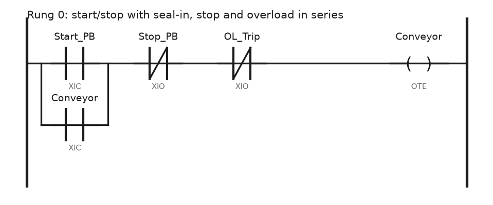
- Create four BOOL tags:
Start_PB,Stop_PB,OL_Trip,Conveyor. - Put an XIC on
Start_PBat the start of the rung. - Branch around it with an XIC on
Conveyor. That branch is the seal-in. - Put an XIO on
Stop_PBafter the branch, then an XIO onOL_Trip. - End with an OTE on
Conveyor.
The stop button is a normally closed contact in the field and an XIO in the program. Wire it normally closed so a broken wire stops the conveyor instead of disabling the stop. That rule has nothing to do with software and everything to do with people, and it is the first thing an experienced person checks in your code. The full worked version with wiring is in motor start/stop programming, and the four contact combinations are in XIC and XIO ladder examples.
Add a timer and a counter
Now make it behave like a machine. The conveyor should run three seconds after the start button, and the job should stop after 50 parts.
Rung 0  Start / stop with seal-in
   Start_PB    Stop_PB   OL_Trip                 Conveyor
  ---] [--+------]/[------]/[-------------------( )---
   Conveyor|
  ---] [---+

Rung 1  Start delay, motor runs 3 s after the command
   Conveyor                                      TON
  ---] [--------------------------------------[ Start_Dly ]
                                               Preset 3000 ms

Rung 2  Motor output
   Conveyor   Start_Dly.DN                       Motor_Run
  ---] [--------] [-------------------------------( )---

Rung 3  Count parts on the rising edge of the photo eye
   Part_PE     ONS                                CTU
  ---] [-------[ONS Part_ONS]-----------------[ Part_Count ]
                                               Preset 50

Rung 4  Job complete latches, operator resets from the HMI
   Part_Count.DN                                 Job_Done
  ---] [-------------------------------------------( )---

Rung 5  Reset the counter
   HMI_Reset_PB                                  RES
  ---] [-------------------------------------[ Part_Count ]
Two things in there trip people up. Start_Dly.DN is the done bit of the timer, and a TON only counts while its rung is true, resetting to zero the moment the rung goes false. And a CTU counts on the rising edge of its rung, which is why the one shot is there: without it, a part sitting in front of the photo eye would add a count every scan, and at a 12 ms scan you would hit 50 parts in under a second.
Siemens does the same job with TON from the IEC timers and CTU from the IEC counters, both needing an instance DB. The behaviour is identical. Instruction detail and more examples are in timer and counter instructions.
Put one button on an HMI
Add a FactoryTalk View ME or WinCC screen with one momentary push button linked to HMI_Reset_PB, and follow one rule: a bit written by the HMI is never written by the PLC. Ever.
Break that rule and you get the classic fight where the operator presses a button, the logic clears it in the same scan, and nothing happens. If the PLC needs to clear an HMI command bit, use a separate handshake: HMI sets HMI_Reset_Req, the PLC acts on it, then the PLC clears HMI_Reset_Req and sets HMI_Reset_Ack. Decide who owns each bit and write it in the tag description. Screen design and tag linking are covered in HMI in PLC systems.
Test it the way a technician would
- Download to the emulator and go to Run.
- Toggle
Start_PBon and off. The seal-in should hold the conveyor on. - Toggle
Stop_PB. Everything drops. - Restart, then toggle
Part_PEfifty times and watchPart_Count.ACCclimb by exactly one each time. - Set
OL_Tripwhile running. The conveyor must drop and stay dropped when you clear it, because the seal-in was broken. - Watch
Start_Dly.ACCcount up in milliseconds. If it sits at zero, the rung feeding it is false.
Step 5 is the one beginners skip, and it is the one that proves the rung actually works.
Six mistakes that cost the first week
Two OTEs on the same tag. Both rungs run, the second one decides, and the first looks broken. Studio 5000 warns about duplicate destructive bits when you verify. Read the warnings.
Latch and unlatch instead of a seal-in. OTL and OTU survive a mode change and a power cycle, which is fine for a fault that must be acknowledged and wrong for a motor. If you latch a motor on, it comes back by itself.
Timer preset in the wrong units. Logix TON presets are milliseconds. 3 seconds is 3000, not 3. On a Siemens IEC timer it is a TIME literal such as T#3s.
Testing with forces and leaving them in. A forced input is a lie the controller tells your logic. Remove the forces before you believe anything, and never leave forces in a running machine.
Editing online without knowing what is running. In Run mode a pending edit does nothing until you accept and finalise it. In the meantime you are looking at code that is not executing.
Writing logic before naming anything. Bit_12 today is a mystery in March. Name the tag for the thing it represents, put a description on it, and your future self stops guessing.
A sensible eight week plan
| Weeks | What to do | Proof you are done |
|---|---|---|
| 1 | Simulator installed, project created, first download | The start/stop rung runs |
| 2 | Bit instructions, seal-in, latch, one shots | You can explain why OTE beats OTL for a motor |
| 3 | Timers and counters, TON, TOF, RTO, CTU | A three station conveyor with delays and part counts |
| 4 to 5 | Analog: scaling, engineering units, alarms | A tank level in percent from a 4 to 20 mA input |
| 6 | Structure: routines, UDTs, one JSR per machine area | The program reads like the machine |
| 7 | HMI: one screen, alarms, a numeric entry | An operator could run your machine without you |
| 8 | Troubleshooting: go online, cross reference, trend a tag | You find a fault someone else planted |
Work through problems rather than reading. The set in PLC programming exercises for beginners is enough material for weeks 2 and 3.
Field notes
The trainee whose counter ran away. A new engineer built a bottle counter without a one shot. On the bench it was fine, because he toggled the input by hand. On the line the first bottle blocked the photo eye for 400 ms and the counter jumped by 33. He had tested the logic, just never at machine speed. Test edge driven logic by holding the input on, not by clicking it.
The stop button that did not stop. A panel was wired with a normally open stop button and an XIO in the program, so the logic was inverted twice and looked correct during the works test. The day a wire came loose at the terminal, the conveyor kept running with the button pressed. Normally closed in the field, XIO in the code. Nothing else is acceptable.
Learning on the wrong hardware. Someone spent three months on a cheap trainer kit with a proprietary language, then joined a plant running ControlLogix and started from zero. If you know which brand your target job uses, learn that one, even if the software is harder to get hold of.
Frequently asked questions
Which brand should I learn first?
Whatever is on the floor where you want to work. In North America that is usually Allen-Bradley, in Europe usually Siemens. The logic transfers between them in a couple of weeks. The habits transfer immediately.
Do I need to learn all five IEC 61131-3 languages?
No. Ladder covers most machine work. Add structured text when you hit maths or string handling, and function block if you do process control. A tour of all five is in PLC programming languages.
Can I learn without buying a PLC?
Yes, up to a point. Everything in this article works on an emulator. Wiring, sinking and sourcing, earth loops, and the smell of a scorched output card need real hardware, and a used Micro850 or an S7-1200 starter kit covers that for less than a good multimeter.
How long until I am employable?
Six months of steady practice gets you to the level where you can maintain existing code under supervision. Writing a machine from scratch on your own is a two to three year job, and nobody serious will tell you otherwise.
What is the difference between an alias tag and a base tag?
A base tag is memory. An alias points at something else, usually a physical I/O point, so Start_PB can mean Local:2:I.Data.0. Alias your I/O and your logic stays readable when the wiring changes.
Next step
Rebuild the rungs above from scratch without looking, then read PLC ladder diagram for the conventions you just used by feel. After that, take a real machine sequence and write it properly, starting from timer and counter instructions and the exercise set in PLC programming exercises for beginners.