MAG and Gearing Two Axes: The Ratio, the Slave, and What Happens on a Fault
A MAG with a Ratio of 0.5 and Clutch enabled, fired at a slave whose master is already running at 600 mm/s, ramps the slave to 300 mm/s in 0.30 seconds at 1000 mm/s² and leaves it permanently 44.9 mm behind where the gearing says it should be. Nothing in the instruction ever gives those 44.9 mm back.
The MAG instruction locks a slave axis to a master’s position at a ratio, and the manual’s phrase for what that lock is worth reading before anything else: a direct edge-to-edge lock, with no maximum velocity, acceleration or deceleration limits used. The slave’s speed is whatever the master’s speed times the ratio comes to.
No limit of the slave’s own applies. That sentence is the whole instruction. So the three decisions that matter are the ratio format, the master reference, and whether the engagement is a clutch or a step — and the fourth thing, the one that comes up at three in the morning, is what a fault on either axis leaves running.
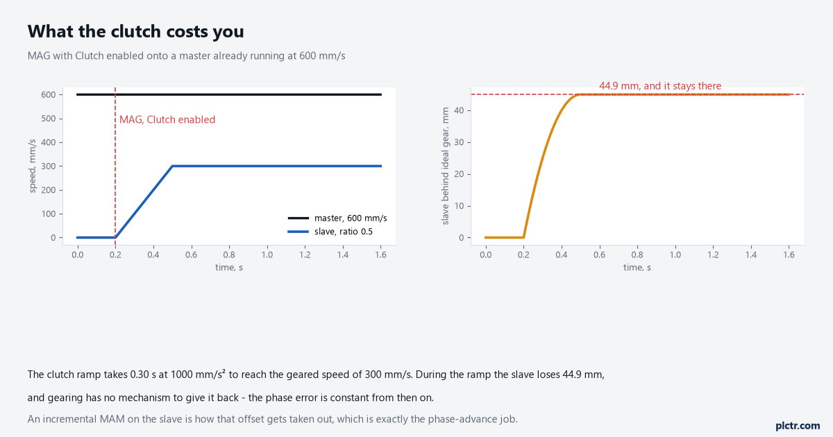
The clutch is what stops an uncontrolled jump when you gear onto a moving master. The price is on the right, and it is permanent until something else takes it out.
The ratio, and why one third has to be a fraction
Ratio Format is a two-way choice and the wrong one is quietly lossy. Set Real and the ratio is a real number between 0.00001 and 9.99999, expressed in the configured position units of the two axes, which is easy to read and easy to check on a drawing. Set Fraction and it is a pair of integers — slave feedback counts to master feedback counts — and the manual is explicit that the axis Conversion Constant is not used at all in this mode. That second sentence is the whole argument. Because the counts are integers and no conversion is applied, the ratio the machine runs is exactly the ratio you asked for, with no accumulated positioning error and no round-off. The manual’s own example is the one that comes up most: a gear ratio of 1/3 can be specified as 1 slave count to 3 master counts, or 10 to 30, or 3 to 9. As a real number it cannot be specified at all. Five decimal places gives you 0.33333, and the error is only in the sixth place, which sounds like nothing until you integrate it over a shift.
Fraction mode ignores the axis Conversion Constant. That is the feature, not an oversight.
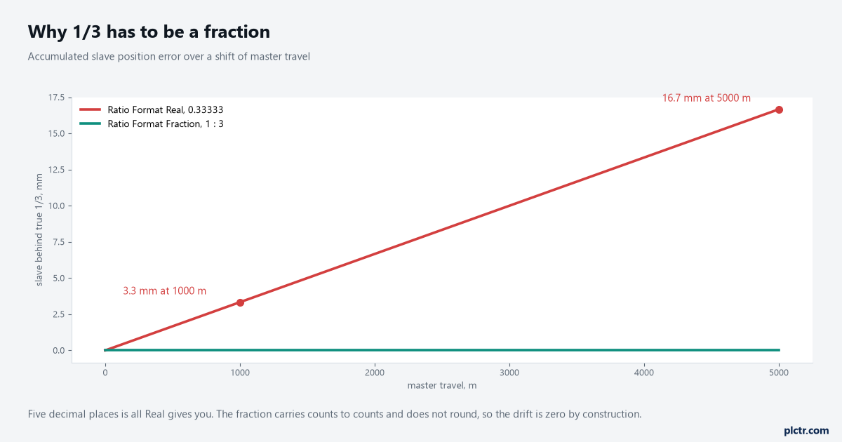
3.3 mm per kilometre of master travel. On a winder that resets every roll it is invisible; on a continuous line it is a register error that grows all day.
Use Fraction whenever the ratio is not exact in five decimals. Use Real when it is, and when someone will have to read it.
Actual position or command position
Master Reference picks which number the slave follows, and the two choices are not interchangeable. Actual position is the master’s position as its own encoder measures it, which includes the master’s following error, any external disturbance to the master shaft, and the quantisation noise of its feedback. Command position is what the master’s planner asked for, and because it carries none of those three, the manual calls it the more accurate and stable reference for gearing. There is a constraint attached to each. Command position is only valid when the master’s Axis Type is Servo, and if you gear to command then the master has to be commanded to move before the slave does anything — turn the master shaft by hand and the slave will not follow.
No command changed, so as far as the slave is concerned the master never moved.
Actual position is the only valid choice when the master is a Feedback Only axis, which is the usual case when the master is a line shaft encoder or a conveyor the servo system does not drive.
Gear to command where you can. Gear to actual where the master is not yours to command.
What a fault leaves running
MAG’s .IP bit is cleared by four things and the manual lists them plainly: another MAG superseding it, a Motion Axis Stop, a merge operation, or a servo fault action on that axis. The words on that axis are doing quiet work there. The exception action configured against each fault on the slave is what decides between them — Disable brings the axis to a stop with the drive’s best available method and clears the gearing, Stop Planner performs a controlled stop at the configured maximum deceleration, and Fault Status Only sets the bit in the axis fault word and instructs the device to do nothing else at all. A slave faulted with Fault Status Only is still geared and still moving, and the manual says in as many words that it is then up to the controller to bring the axis to a stop programmatically. That is a defensible configuration on a machine where an uncommanded stop is worse than the fault, and an indefensible one if nobody wrote the rung that does the stopping.
Fault Status Only means the rung you did not write is the stop.
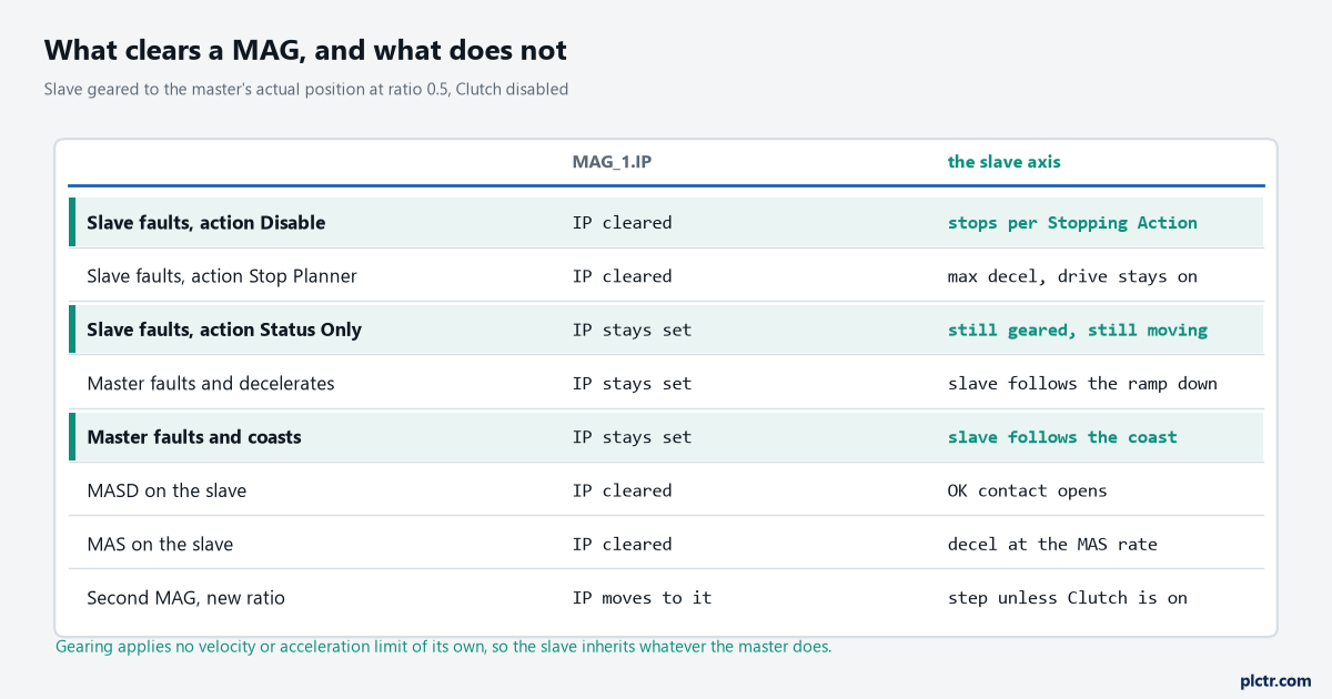
The three highlighted rows all end with the slave still moving. Gearing has no limits of its own, so whatever the master does, the slave does at the ratio.
A fault on the master axis is not a fault on the slave.
The slave’s .IP stays set and the gearing stays active, and the slave keeps tracking whatever the master’s position does next. If the master’s exception action decelerates it at its maximum rate, the slave rides that ramp down at the ratio, which is usually what you want. If the master’s action is Disable and its Stopping Action is Disable and Coast, the master’s shaft coasts — and a slave geared to the master’s actual position follows that coast all the way to standstill, however long the inertia takes. A slave geared to the master’s command position does not: the planner has stopped issuing commands, so the slave stops even while the master shaft is still turning. Two identical machines with one different enumeration behave differently in the same fault.
Fault the master deliberately on a bare machine and watch what the slave actually does.
Do it before a real fault asks the question for you, with product in the machine.
Changing the master, and the pair that cross-couples
The master axis can be changed at any time, including while gearing is active, and the manual pairs that freedom with a warning worth quoting in shape if not in words: because gearing can be enabled on more than one axis at a time, reversing a servo master and slave without disabling the first relationship leaves the two axes cross-coupled, and unexpected motion may result. Gearing Axis 0 to Axis 1 and then deciding to gear Axis 1 to Axis 0 does not undo the first arrangement. It adds a second one. Disable the gearing on the first slave before you make it a master.
The direction operand has a Disable choice, and an MAS on the axis does the same job. The related error to know is .ERR 10, Master Axis Conflict, which is what you get when the master reference is the same as the slave reference. .ERR 11 is Axis Not Configured, and its extended code tells you which end is at fault.
One means the slave axis. Two means the master.
One more that catches people on a new machine: MAG needs the slave in the Servo On state.
Fire it at an axis that is configured but not enabled and it errs with 5, Servo Off State Error, whose printed corrective action is simply to close the servo loop first. That is MSO’s job, and on a two-axis gear pair both axes need it.
The move that rides on top of the gear
Electronic gearing stays active through any subsequent jog or move on the slave, which is the mechanism behind phase advance and retard. Superimpose an incremental MAM on a geared slave and the slave takes that distance on top of whatever the gearing is asking for, which is how you take out a phase error — including the 44.9 mm the clutch cost in the first figure — or how you deliberately create a non-zero phase relationship. The manual adds two pieces of guidance around it that are easy to lose. A ratio of 1 is normally used with phase adjustment.
At 1:1 the computed phase error does not change while the correcting move is executing, which is the point. And gearing is not normally combined with absolute moves, because the endpoint of an absolute move on an axis that is also being driven by a master is not predictable. Incremental for phase, absolute almost never. Anything you need to know about how that move behaves is in MAM against MAJ, and it behaves no differently for being superimposed.
Next thing to do: trend the master command position, the slave command position and the arithmetic difference between them at the ratio, then engage the clutch once and read the offset off the trend. That number is your phase error, and an incremental MAM of exactly that size takes it out. If the two axes in question are conveyor sections rather than servos, speed matching across a transfer solves the same problem with drives instead of gearing, and the walkthrough from motion group to first move covers the setup both approaches assume.