The Motion Group and the Coarse Update Period: What Happens When You Ask for Too Much
Bit 2 of MOTION_GROUP.GroupFault is GroupTaskLoadingFault, and the motion instruction reference describes it in plain words: the group coarse update period is too low, and user application tasks are not getting enough time to execute. That is a 1756-L84E telling you that the 2.0 ms you typed is not affordable with the axes you have put behind it.
Bit 0 is GroupOverlapFault — the Motion Task has run into itself. Bit 1 is CSTLossFault. Those three are the whole vocabulary for “too much”, and the useful part is that two of them are about time rather than about the network, which is where people look first.
The fix is almost never a smaller number. It is fewer axes updated at the fast rate.
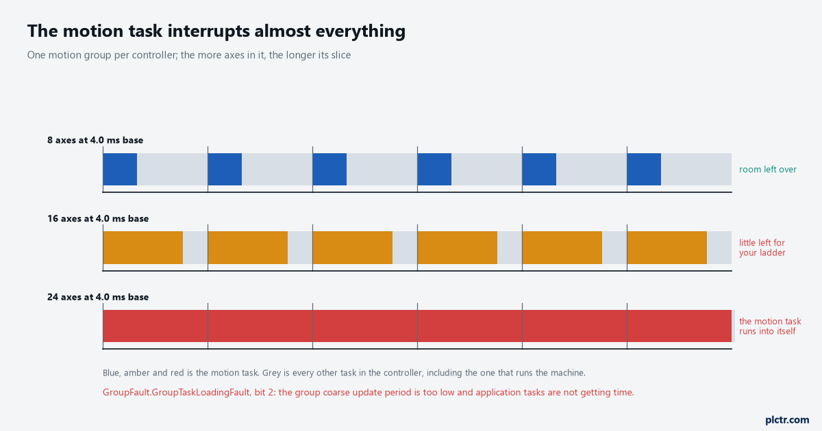
The grey is your machine logic. The coloured block is what the motion group costs before a single rung executes.
Two names, one number
The dialog and the manuals do not agree on what to call it, and both names are current.
On the Attribute tab of the Motion Group Properties dialog the field is Base Update Period. In the motion instructions reference and the Integrated Motion reference manual the same interval is the coarse update period — it is the phrase used in the description of GroupTaskLoadingFault, in the definition of Average Velocity Timebase, and everywhere the resolution limits on command and actual velocity are stated. Same number, two vocabularies, and knowing both is the difference between finding the answer and not. What it actually is: the request packet interval of the unicast motion connection between the controller and the drive, and the interval at which the Motion Task runs. The Motion Task is the part of the controller that maintains position and velocity for every axis in the group, and when it runs it interrupts most other tasks regardless of their priority. So the period is two things at once — a network rate and a scheduler slot — and the second is where the trouble comes from.
There is exactly one motion group per Logix controller. One number, then, for everything that moves.
What the controller does inside each period
The exchange is not the same on every controller, and the field that tells you is read-only.
Timing Model on the Attribute tab shows either One Cycle or Two Cycle, and the manual’s table is short: a 1756-L7 or a 1769-L and earlier is One Cycle, a 1756-L8 and a 5069 and later are Two Cycle. Under the One Cycle model one device-to-controller packet is sent for every controller-to-device packet received, the controller task runs at a phase offset of roughly 330 µs into the period, and the drive’s own update period — the rate at which it does its control calculations — is typically much faster than the controller’s, 250 µs in the manual’s figure. The Two Cycle model starts with the drive transmitting its device-to-controller packet at the beginning of the cycle and then does not start the controller task until halfway through, which gives that packet more time to arrive; the reply is not sent back until the next time the Motion Planner runs, so it takes two connection cycles to complete one data transaction. The phase offset is around 500 µs. What you buy with Two Cycle is tolerance for network delay. What you pay is one period of latency in the loop, and on a 1756-L8 you do not get a choice.
The floors, the ceiling, and the floor that moves
Three numbers bound the field, and one of them is not printed anywhere.
The range is 0.5 to 32 ms, and entering something outside it produces a warning and clamps the value to 0.5 or 32. The per-drive minimums are lower bounds on top of that: an Axis CIP Drive will accept 1 ms, a PowerFlex 755T wants 2 ms, a PowerFlex 755 wants 3 ms and a PowerFlex 527 wants 4 ms, so one PowerFlex 527 in a group of Kinetix 5700 axes sets the base for all of them unless you schedule it separately. The base is editable offline and read-only online. And then the one that is not a published number: the manual says outright that if the base update period is too small the controller does not have time to execute non-motion ladder, and that the configuration therefore sets the lower limit on the base update period based on the number of axes in the group. The floor moves as you add axes, and nobody tells you where it has moved to.
Too many axes at one rate shows up as one of two things, and the manual names both: not enough time for the motion task to execute, which gives you a motion task overlap error, or high application program scan times that degrade all of your logic, not just the motion part.
The second one is the quiet failure. Nothing faults; the machine simply gets slower and vaguer.
Reading the utilisation numbers instead of guessing
The Axis Schedule Panel carries five meters that update in real time as you change the configuration, and they are the only honest answer to “is this too much”.
Task I/O Cycle is the estimated percentage of Logix controller time the motion task consumes; a warning icon appears above 50% and an error icon above 80%. Connection I/O Cycle is the percentage of the time available in the update cycle used to process input, run the motion planner and send output to the drives, and it warns above 100%. Communications is the comms processor’s share of the motion connection packets, warning above 50% and erroring above 100%. Ethernet Media is the share of media bandwidth those packets use, warning above 50% and erroring above 100%. Two of those four are about the controller and two are about the network, which is exactly the distinction that gets lost when somebody decides the switch is the problem. The fifth thing to read is the pair of Estimated and Actual columns: estimated utilisation assumes a basic configuration with no active motion planner activity, no transmission statistics and no cyclic read or write, and the manual warns that actual utilisation — measured by the controller — can be substantially higher. Estimated is a design-time guess. Actual is what your machine does with real profiles running.
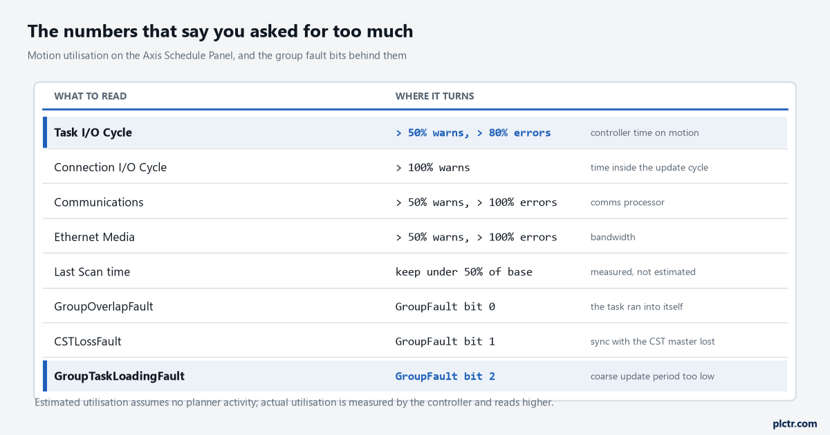
Four meters and three bits. Only two of the meters are about the network, which is the opposite of where most of the troubleshooting goes.
Alongside those, one rule of thumb that costs nothing to check: keep the Last Scan time under 50% of the base update period, and keep the Motion Task under half the controller’s time on average. If you are chasing a slow machine rather than a motion fault, measuring the scan properly first separates the two problems before you start changing periods.
Three rates instead of one
Axis scheduling is the answer to almost every “too much” on this list, and it is under-used because it is two clicks further in than the Attribute tab.
The worked example in the manual is a robot lifting product off a conveyor: three precision axes on the robot, four general-purpose axes on the belt. Running all seven at 2 ms to satisfy the robot pushes network utilisation too high; running all seven at 8 ms is not precise enough for the robot; and the historical answer was a second controller and a second Ethernet module. Axis scheduling gives you a base rate plus two alternates, and the alternates are whole multiples of the base from 2 to 32 — so a base of 2.0 gives alternates of 4, 6, 8 and upward, and a base of 3.0 gives 6, 9, 12. Put the robot on the 2 ms base and the conveyor on an 8 ms alternate, and the four conveyor axes multiplex through one drive update channel: they look to the controller like a single drive, updated round-robin, one of them per base period. The controller handles the load of four axes rather than seven while the robot still gets its 2 ms.
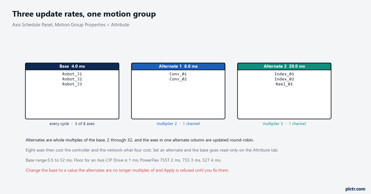
Eight axes, three rates, and the controller carrying what five would cost it. The alternate columns are the part of this dialog most projects never open.
Two mechanics catch people the first time. Once an alternate rate is set on the Axis Schedule Panel, the Base Update Period on the Attribute tab is disabled and you set the base on the panel instead; set all three rates to the same value and the Attribute tab’s field comes back. And if you change the base to a value the alternates are no longer whole multiples of, a warning flag appears next to the offending rate and clicking OK or Apply is refused until the alternates are valid again.
The one that hides in an instruction
Output cams are the specific case where a group that was comfortable stops being comfortable, and the manual is unusually direct about it.
An important note on the MAOC instruction says output cams increase the potential for exceeding the coarse update rate, that this causes misbehaviour if the motion task execution time exceeds the configured group coarse update period, and — the useful half — that the only way to check for the condition is to monitor the max execution time in the Motion Group Properties dialog. That is a specific place to look that nothing else points you to. The instruction also slices the period internally: it divides the coarse update period into sixteen time slots and assigns cam on and off events to slots by their position within the period, so a 2 ms coarse update yields sixteen 125 µs slots. If a cam element’s latch and unlatch land in the same slot they cancel each other out, which means the minimum usable pulse width of a cam element is one slot — longer coarse update, coarser cam resolution, and a pulse that was fine at 2 ms may vanish at 8 ms.
Lengthening the base to fix a loading fault can therefore break a cam that was working. Check both.
What to do on Monday
Go online, open the Motion Group Properties, and read Actual Utilisation rather than Estimated. Note Task I/O Cycle and the max execution time, and compare Last Scan against the base. If Task I/O Cycle is over 50% and the machine has axes that genuinely do not need the fast rate — indexers, reel drives, anything point-to-point — move those onto Alternate 1 or Alternate 2 before you touch the base at all. Changing the base is the move that affects every axis, every output cam and every velocity resolution limit in the group, and it should be the last thing you try rather than the first.
Then write the resulting schedule into the project documentation, because the next person to add an axis to this group needs to know which column it belongs in. If the axes in question are on a Kinetix 5700, the electrical side of the same headroom question — how many the bus supply will carry — is in the DC bus sharing limits, and a first MAM on a Kinetix axis is where the update period stops being an abstraction.