Kinetix 5700 DC Bus Sharing: What the Bus Supply Carries and Where the Limit Is
A 2198-P208 supports 13,000 µF of total system capacitance and puts out 46 kW continuously. Those are two separate ceilings, they get reached by two different kinds of machine, and on most rails the one that stops you first is neither of them — it is the 40 A on the 24V control bus or the 1200 m of summed motor cable.
Four limits, then, and all four are arithmetic you do on paper before anything is ordered. Capacitance against the supply’s supported maximum. Continuous kW against the supply’s rating. The sum of every motor power cable on the group against 1200 m. And the 24V control current against 40 A. Nothing in Logix Designer computes any of them. Three of the four are not on the datasheet page you are reading, which is why they get skipped.
The seven-module example rail printed in the Kinetix 5700 user manual sits at 4840 µF, 337 m and 20.3 A, which is why it works.
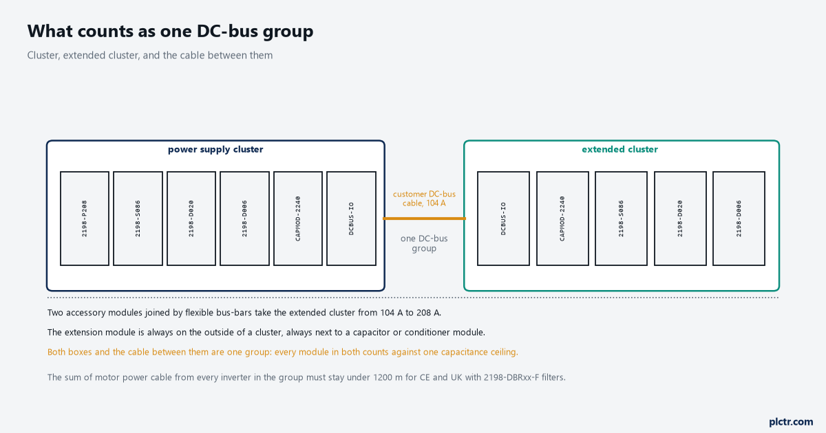
The cable between the two boxes is what makes them one group rather than two systems. Everything on both sides of it counts against one supply.
The four words the manual uses, and why they are not the same word
Getting the vocabulary right saves an argument with the person doing the sizing.
A DC-bus group is every drive module connected to the same DC bus, wherever it physically sits. A cluster is narrower: modules directly connected to each other by Kinetix 5700 DC bus bars only. The power supply cluster is the cluster containing the AC-to-DC converter, and an extended cluster is a group of modules joined to each other by bus bars and joined to the power supply cluster by customer-supplied DC-bus cable. So a machine can be one group made of two clusters sitting in two enclosures, and that is a supported arrangement rather than a bodge — the DC bus gets out of the first cluster through the connection points on an accessory module and travels on cable you supply and size yourself. The manual adds one attention note that is easy to skip and expensive to skip: circuit protection can be added after the power supply cluster, to protect the converters and inverters if that DC-bus cable ever shorts.
Four sources can feed the bus: a single 2198-Pxxx, up to three 2198-P208 in parallel, a single 2198-RPxxx regenerative bus supply, or multiple 8720MC-RPS regenerative power supplies.
When there are two or three DC-bus power supplies wired into the same cluster, they must all be 2198-P208. Not a mixture.
The capacitance ceiling, and the three ways past it
Total system capacitance is the sum of the internal capacitance of every module on the group, and it has to come out below the supply’s supported maximum.
The supported figures are short enough to remember. A 2198-P031 or 2198-P070 supports 8000 µF. A 2198-P141 or a 2198-P208 supports 13,000, two 2198-P208 in parallel support 26,000 and three support 39,000. On the regenerative side a 2198-RP088 supports 9000, a 2198-RP200 supports 15,000, and a 2198-RP263 or 2198-RP312 supports 25,000. The supplies bring their own capacitance to the total they have to carry — 2050 µF for a 2198-P208, 5740 µF for a 2198-RP312 — so a large regenerative supply spends a fifth of its own ceiling before an inverter is added. Against that, the inverters are modest: 165 µF for a 2198-D006 or 2198-D012, 330 for a 2198-D020, 390 for a 2198-D032, 705 for a 2198-D057, and on the single-axis side 560, 840, 1120 and 2050 µF as you climb from the 2198-S086 to the 2198-S312. The extension module and the DC-bus conditioner module contribute nothing at all. The capacitor module contributes 2240 µF on its own, which is more than any single inverter except the two largest, and that is the trade it exists to make.
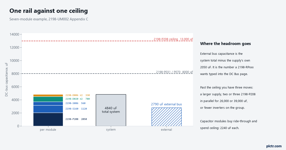
Seven modules use just over a third of a 2198-P208’s ceiling. Two capacitor modules would use another third without adding an axis.
Go over the ceiling and the manual gives exactly three moves: fit a larger DC-bus power supply or regenerative bus supply, go to multiple supplies, or bring the total down by taking inverters or capacitor modules off the group. There is no fourth option and no tolerance to argue about, because the number is a precharge limit — the supply has to charge all of that capacitance at power-up, and the maximum number of inverters a system can carry is described in the manual as depending on the precharge capability of the supply against the total system capacitance. A 2198-P208 that fails to charge its rail gives you FLT S25 PRECHARGE FAILURE rather than a helpful message about sizing. External bus capacitance is the same total with the supply’s own contribution subtracted: 4840 minus 2050 is 2790 µF on the example rail. That figure is not a check, it is an entry — a 2198-RPxxx regenerative bus supply wants it typed into the DC Bus page by hand, and the consequences of letting it go stale are in what changes when an axis comes out of a commissioned system.
The ceiling is a precharge figure, not a comfort margin, and nothing negotiates with it.
The power ceiling, and the estimate that gets you close enough to order
Capacitance says how many modules fit. Continuous output power says whether they will do any work.
The DC-bus supplies run 7 kW for a 2198-P031, 17 kW for a 2198-P070, 31 kW for a 2198-P141 and 46 kW for a 2198-P208. The regenerative family starts higher and goes much higher: 24 kW on a 2198-RP088, 67 kW on a 2198-RP200, 119 kW on a 2198-RP263 and 140 kW on a 2198-RP312. Parallel 2198-P208 modules exist to raise that converter figure, which is the other reason for the three-supply arrangement.
There is a rough sizing formula printed alongside those numbers, and it is more useful than its reputation suggests:
2198-Pxxx minimum continuous output power (kW)
    = largest motor-rated kW x (axis count x 0.6) + (axis count x 0.2)
The manual’s own worked case is eight axes whose largest motor is an MPM-B2153F at 7.2 kW, giving 7.2 × (8 × 0.6) + (8 × 0.2) = 7.2 × 4.8 + 1.6 = 36.16 kW, and concluding that a 2198-P208 or a 2198-RP200 covers the system. Note what the formula keys off: the largest motor in the system, not the sum of the motors. Eight small axes and one big one is sized by the big one. The manual is equally clear that this is an approximation and should not be used for final sizing — the real answer comes from FactoryTalk Motion Analyzer with the actual load profiles, and the torque and speed curves in the Kinetix 5700 Drive Systems Design Guide. Use the formula to decide which supply to price. Use the tool before anybody buys it.
The two ceilings that have nothing to do with power
Both of these get missed because they are not on the drive datasheet you are reading.
The first is cable. The sum of the motor power cable lengths for every inverter on the same DC bus-sharing group must not exceed 1200 m to meet CE and UK requirements when 2198-DBRxx-F line filters are used, and it drops to 400 m total with the 2198-DBxx-F filters — a different part number, three characters apart, with a third of the allowance. That is a whole-group figure, not a per-drive figure, so twelve axes averaging 90 m of cable is already past the smaller limit and comfortable under the larger one. The second is 24V. If you distribute control power along the rail with the 24V shared-bus connection system, the output current from that supply must not exceed 40 A, and the worked example reaches 20.3 A on seven modules with three motor brakes on it. Brake current is on top of the per-module figures, and it is not small: 2.1 A for one of the motors in that example.
Both limits fall on the whole group, and both tend to get checked only after something misbehaves.
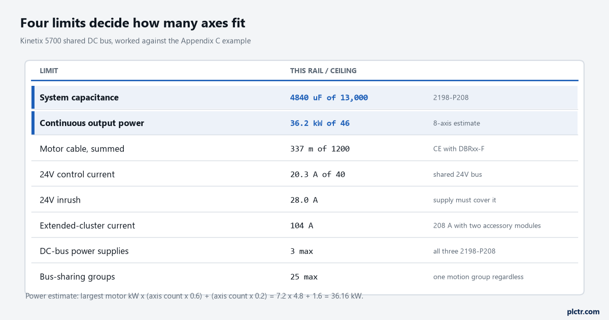
One page of arithmetic decides the supply. Doing it after the panel is built decides it too, just more expensively.
Where the bus leaves the cluster, and what that costs
An accessory module is how DC bus gets from one cluster to the next, and its rating is the constraint.
One accessory module — a 2198-CAPMOD-2240 capacitor module or a 2198-DCBUSCOND-RP312 conditioner module — extends the external DC bus in applications up to 104 A. Two of them mounted side by side and joined by two flexible bus bars take that to 208 A. The 2198-CAPMOD-DCBUS-IO extension module is the part that makes the pair work above 104 A, and it is the only one of the three that ships with the flexible bus bars in the box: two capacitor modules together, or a capacitor and a conditioner together, need the 2198-KITCON-CAPMOD2240 or 2198-KITCON-DCBUSCOND connector set ordered separately. All three accessory modules are 55 mm wide and rated 276 to 747V DC nominal. On a regenerative system the conditioner module is not optional in two cases: every extended cluster needs one, and the power supply cluster needs one as soon as the motor cable connected to that cluster reaches 400 m. So an extended cluster costs you two module slots on each side of the cable, 110 mm of rail each, plus whatever the capacitor module adds to the capacitance total. Where those modules sit on the rail is fixed rather than free, and the module order and the drill-hole pitch is where that ends up mattering.
Build the ledger before you price the supply
One sheet, one row per module: catalogue number, internal capacitance, 24V current, 24V inrush, motor cable length. Sum the four numeric columns. Put the supply’s supported capacitance, its continuous kW, 1200 m and 40 A in a box at the bottom and compare. Then run the kW estimate off your largest motor and the axis count, and if the answer lands within about 20% of a supply’s rating, go to Motion Analyzer rather than rounding in your favour. Keep that sheet in the project folder, because it is the document that has to be edited every time an axis is added to the group and the only record of what the original sizing assumed. If you are choosing between a drive-per-motor arrangement and a shared bus in the first place, how a PLC drives a motor through a VFD or a servo is the wider comparison to have made first.