The 1756-OBV8S Safety Output Card: What a Pulse Test Does to a Contactor
Point 3 of a 1756-OBV8S flashes red while its output is off, and the contactor it drives is behaving perfectly. That is no-load detection, and it is telling you the truth: something between OUT3-P and the coil has come apart. The detection needs at least 10 mA to see a load, it only runs while the output is off, and the output has to stay off for a minimum of 300 ms before the card will report anything.
On a machine whose safety outputs are on for eleven months a year, that is a diagnostic which almost never gets a chance to run.
This is the 1756-OBV8S in a GuardLogix chassis, with the numbers from the digital safety I/O user manual and the ControlLogix I/O specifications.
What the pulse test actually does to a contactor
The output is commanded on the whole time. The gaps are the card proving it can still switch off.
With Point Mode set to Safety Pulse Test, a 1756-OBV8S drops each on output for under 750 µs at a period under 96 ms, and looks to see whether the terminal actually went low. What that catches is a short to 24 V that would otherwise leave the output stuck on with the safety function asking for off. A 100S contactor coil cannot drop out in 750 µs and never notices; anything faster between the card and the coil can. There is a second number that matters when you are watching a trace and expecting an instant answer: two successive output pulses are required before the module declares a short circuit, so the effective pulse period is up to 192 ms and the fault arrives that long after the defect. The manual adds a warning worth taking literally — an open wire test and a main switch pulse test can put a pulse on a safety output even in safety mode, so the pulses on the scope are not always the ones you configured.
If the load is a solid-state relay or an electronic input rather than a coil, the chattering problem and its fix are covered in test pulses on a safety output, which works through the same mechanism on the Guard I/O family.
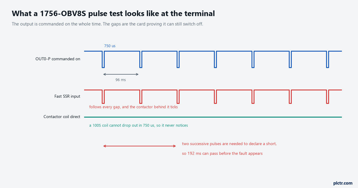
Two successive pulses before a fault is declared. That is why a shorted output is not reported in the same scan it happens.
Bipolar or sourcing, and the pairs you do not choose
This is the decision that gets made at the drawing stage and cannot be changed later without rewiring.
In Bipolar mode a channel is a P and M pair: the card sources one side of the load and sinks the other, one load per channel, and every channel is single-channel Point Operation Type. In Sourcing mode the M terminals go to DC negative, the P terminals drive the loads, and you get a choice of single or dual channel. Dual channel only exists in sourcing mode, the pairs are fixed at 0 and 1, 2 and 3, 4 and 5, 6 and 7, and both channels of a pair must always be in the same logical state. Rockwell recommends configuring dual channel for dual channel applications outright, on the grounds that it lowers the dangerous undetected failure rate inside the module. Here is the part that surprises people who assume more channels is always better: as drawn in the specifications, a single bipolar channel reaches Category 4 and PL e, while a single sourcing channel is listed up to Category 2 and PL d, and sourcing needs the pair to get to Category 4. Switching one side of a load and being able to prove both ends is worth more than two outputs switching the same side.
Bipolar buys the rating with a catch printed next to it.
A no-load fault in that arrangement is only detectable if the wires from both the P terminal and the M terminal are disconnected — one wire off does not show — and the specification strongly recommends separate shielded cables to the P and M terminals to reduce the chance of a short between them. There is a second recommendation for anyone whose output module and input module sit on different 24 V supplies: bond the module DC negative to the actuator DC negative, because grounding float is enough to upset the diagnostics.
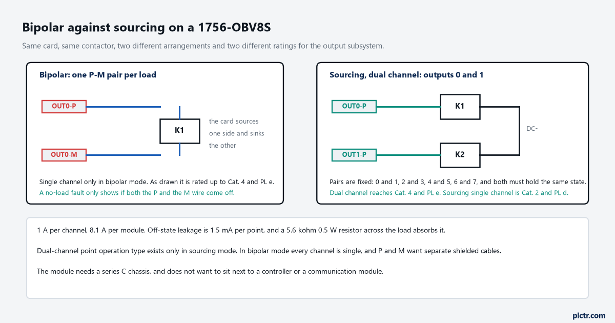
Same card, same contactor. The arrangement decides the rating, and the arrangement is fixed the day the loom is made.
Single channel, and the two conditions that come with it
Single channel is allowed. It is allowed with a condition most people never read.
The manual certifies single-channel mode only for functional safety applications with a process safety time of 200 ms or more, or for applications with a demand rate no higher than three demands per minute. Those are not arbitrary — they are the assumptions the diagnostic rate was calculated against, given that a short takes up to 192 ms to be declared. A guard on a machine that gets opened four times a minute during a changeover is outside that envelope on the second clause alone, whatever the process safety time says. Nothing on the card enforces it. The number lands in the safety file, and it is the kind of assumption that quietly stops being true when the product changes and the cycle speeds up.
Write the demand rate in the safety file, not just the category.
When the output is off for months
There is a recommendation for Category 4 applications that reads like it was written after a site visit.
If the application stays in its safe state — output off — for a prolonged period, the specification suggests one of three things: monitor the output at the actuator, directly or indirectly; limit the safe state to no more than 24 hours; or run a functional test if the dwell time in the safe state increases. It is the mirror image of the no-load problem in the opening: the pulse test runs when the output is on, the no-load check runs when it is off, and an output that lives permanently in one state gets only half the diagnostics. Monitoring at the actuator is what an EDM and mirror contact arrangement gives you, and it is worth the extra pair of terminals precisely because it does not care which state the output has been sitting in.
A card diagnostic proves the card. The mirror contact proves the contactor.
What recovers, and what needs a power cycle
Three field faults clear themselves once the cause is gone, and one diagnostic does not.
Field power off, short circuit to ground and overload all recover, with the recovery time being one second for field power and ten seconds for a short or an overload; field power loss on this card includes undervoltage and overvoltage on the DC bus, not just a missing supply, and it can need up to two seconds to complete the recovery. Whether the fault status clears on its own depends on the module-level Latch Fault until reset via output tag setting: enabled, the channel waits for a rising edge on ResetFault in the consume assembly; disabled, which is the default, it holds for a second and then clears when the consume data bit is low. The exception is the one to remember at three in the morning — an output that was shorted to 24 V when the thermal shutoff or short circuit condition was detected needs a power cycle of the module before the diagnostic itself will reset, even after the short has gone. And a fault on one output can take the whole card’s outputs off, which is a design consideration if you have put two independent zones on one module.
Reaching for a power cycle first is a habit worth resisting everywhere except here.
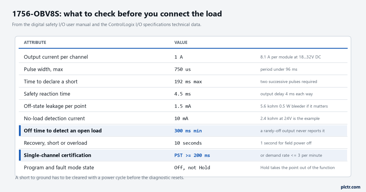
The two highlighted rows are the ones that decide whether a diagnostic ever runs on your machine, rather than whether it exists.
The setting that takes the point out of the safety function
Output State During Program Mode and Communications Fault Mode has two values, and only one of them is a safety output.
Off is the default and it is the one to keep. Hold prevents the output point from going to its safe state, and the manual says in plain words that a point configured to Hold is not suitable for a SIL or PL rated safety function — the whole TÜV approval of the controller family rests on the de-energised state being the safe state. It is a per-channel setting, which is exactly how a mistake survives a review: seven channels correct, one set to Hold because somebody wanted a lamp to stay lit through a program-mode download. The module follows the mode of the safety task rather than the controller, too, so an unhandled safety fault can put these outputs into Program mode behaviour while the standard tasks keep running.
There are a few installation facts that belong on the order rather than in the commissioning: the card needs a Series C ControlLogix chassis, takes a 1756-TBNHS or 1756-TBSHS terminal block at 1.36 N·m, pulls 280 mA from the 5.1 V backplane, and dissipates enough that the specification tells you not to put it next to a controller or a communication module.
Next step: on a card already in service, check the Output State setting on every channel and the Point Mode on every channel, then find out how long your safety outputs actually sit in the off state. If the answer is “only during a fault”, the no-load diagnostic has never run on that machine and the mirror contact is doing all the work. The input side of the same chassis is covered in the 1756-IB16S safety input card, and what the reset has to look like is in a safety reset that is a rising edge.