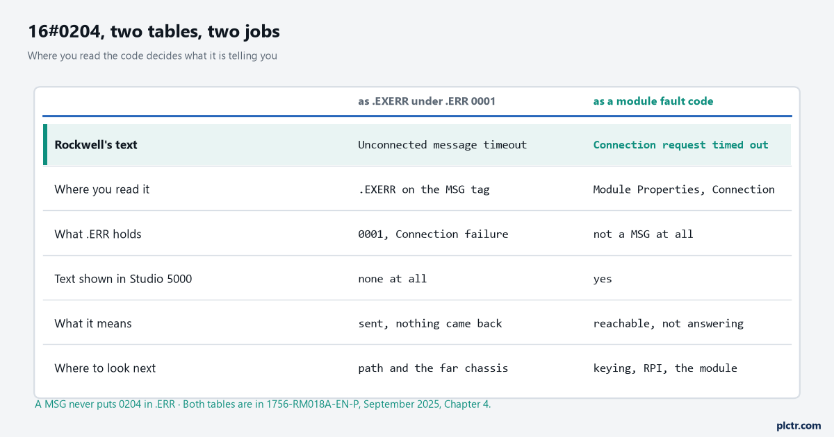
16#0204 appears twice in the same Rockwell reference manual with two different meanings, and which of the MSG instruction error codes tables you are reading decides where you spend the next hour. In the extended error codes for error 0001 it is Unconnected message timeout. In the module fault codes it is Connection Request Error: Connection request timed out, and the explanation that goes with that one is a paragraph long.
So the first thing to sort out is which of your two members is actually holding that 0204.
A MSG does not put 0204 in .ERR. It puts 0001 there — Connection failure — and 0204 lands in .EXERR, where Studio 5000 shows you nothing at all. The manual states that plainly: the Logix Designer application does not display any text for the extended error codes. You get a number, no string, and most of the time nobody realises there are two members to look at.
A MSG that works needs four things right, and in this order: the message type, the path, its own MESSAGE control tag, and a rung that toggles it rather than holding it true. Everything below is one of those four.
Where the MSG instruction error codes live now
If you go looking for the MSG error tables in 1756-RM003, you will get the document — but it is not called that any more.
Every page footer of the current edition reads 1756-RM018A-EN-P, September 2025, and the back page says it supersedes 1756-RM003Z-EN-P, September 2024. Same manual, Logix 5000 Controllers General Instructions, new publication number as of this revision. Worth knowing before you go asking a colleague for “the RM003” and get told it does not exist.
The error tables are still in it, incidentally. Rockwell has moved plenty of fault tables out to a knowledgebase spreadsheet, and the MSG codes in Chapter 4 are not among them.
Pick the message type before anything else
Get this wrong and the path never gets a chance to be wrong.
| Target | Message type |
|---|---|
| Another Logix 5000 controller | CIP Data Table Read / CIP Data Table Write |
| An I/O module you want to reconfigure online | Module Reconfigure |
| A CIP device with no Logix-shaped tags | CIP Generic |
| SLC 500 or MicroLogix | SLC Typed Read / Write |
| PLC-5 | PLC-5 Typed Read / Write, or Word Range Read / Write |
| Block transfer module on remote I/O or ControlNet | Block Transfer Read / Write |
CIP Data Table Read and Write transfer data between Logix 5000 controllers, and the manual attaches one condition to both that catches people: the source and destination types must match. A DINT array read into an INT array is not a conversion, it is a fault.
Module Reconfigure is the one nobody knows exists, and it is worth ten minutes of your afternoon.
It sends new configuration information to an I/O module while the module keeps running — input modules continue sending input data to the controller, output modules continue controlling their output devices. That is how you change an alarm limit on an analogue card without dropping the connection.
And there is a recommendation attached to both CIP types that is easy to skip. For most applications Rockwell advises leaving CIP data table messages, and CIP generic messages, unconnected.
The path, and the table Rockwell drew badly
A path is pairs. Port, then address, then port, then address, for as many hops as it takes to get out of your chassis and into theirs.
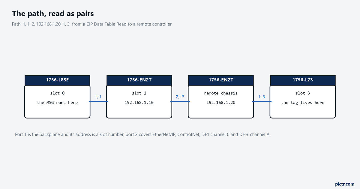
The port numbers are in 1756-RM018 in a table with merged cells, and the merge is why half the internet is unsure about this. Read the vertical spans rather than the rows and it comes out clean. Backplane is port 1. A single “2” spans four network rows — DF1 on serial channel 0, ControlNet, EtherNet/IP and DH+ channel A. A single “3” spans DH+ channel B and DF1 channel 1. So the Ethernet port on your bridge module is port 2, and it is port 2 on a DH+ channel A card too, which is the part that looks like a typo until you notice where the cell boundaries fall. The addresses then depend on the network, and the manual is specific about each of them. Backplane address is the slot number of the module. ControlNet is a node number, 1 to 99 decimal. DH+ is a node number written in octal with a prefix, so node 37 octal is typed as 8#37. EtherNet/IP takes any of four forms: an IP address such as 10.10.10.10, an IP address with a port such as 10.10.10.10:24, a DNS name such as tanks, or a DNS name with a port. There is also THIS, which is a path to self and is how you send an unconnected message to your own controller — that is the path in Rockwell’s own CIP Generic example for reading the number of unconnected buffers, Service Code 3, Class 304, Instance 1, Attribute 0.
So a typical two-hop path out of a 1756-L83E, through a 1756-EN2T in slot 1, to a controller in slot 3 of a remote chassis, reads: 1, 1, 2, 192.168.1.20, 1, 3. Backplane to slot 1. Ethernet port to that IP. Backplane at the far end to slot 3.
Do not type any of it by hand if you can avoid it.
Use the Browse button on the Communication tab and pick the remote controller out of the tree, and Studio 5000 writes the path for you from the I/O Configuration entries. Hand-typing is where the extra hop goes missing and where somebody puts the local bridge’s IP address in as the destination, which produces a MSG that times out against a card sitting six inches away. If the remote controller is not in the tree to be browsed, add it the ordinary way first — bridge, chassis, controller — the same tree that produced and consumed tags need, for the same reason.
There is one useful oddity in the path member itself. .Path is a STRING, and if you ever write it from logic the manual wants hexadecimal with no commas: a path of 1, 0, 2, 42, 1, 3 is entered as $01$00$02$2A$01$03. Which is exactly the sort of thing you write once, comment heavily, and never touch again.
Two members, two tables
.ERR is an INT. .EXERR is an INT. Look at both, every time.
These are the .ERR values that come back most often, quoted from the error code table in 1756-RM018:
| .ERR | Description |
|---|---|
| 0001 | Connection failure (see extended error codes) |
| 0004 | IOI syntax error (see extended error codes) |
| 0005 | Destination unknown, class unsupported, instance undefined or structure element undefined |
| 0006 | Insufficient packet space |
| 0007 | Connection lost |
| 0008 | Service unsupported |
| 00D1 | Module not in run state |
| 00FE | Message timeout |
| 00FF | General error (see extended error codes) |
Three of those say “see extended error codes” and that is not a formality.
It is where the answer is. For 0001 the extended list runs 0100 Connection in use, 0106 Ownership conflict, 0107 Connection not found, 0108 Invalid connection type, 0109 Invalid connection size, 0110 Module not configured, 0111 EPR not supported, 0114 Wrong module, 0115 Wrong device type, 0116 Wrong revision, 011A Application out of connections, 0203 Connection timeout, 0204 Unconnected message timeout, 0206 Message too large, 0301 No buffer memory, 0311 Port not available, 0315 Invalid segment type.
Read that list and the diagnosis narrows quickly. 0109 is a size argument. 0116 is a firmware revision against Exact Match keying. 011A is the controller having run out of connections entirely, which is a different problem from anything on the wire. And 0204, the one people quote, is the controller saying the request went out and nothing came back — no refusal, no error from the far end, just silence.
For .ERR = 00FF the extended list is a different set entirely, in the 2000s, and two of them are worth memorising because they are the everyday ones. 210B, Symbol does not exist — the remote tag name is wrong, or it is program-scoped at the far end when a MSG can only reach controller-scope tags. 2105, Address and how many out of range — you asked for more elements than the destination array holds. Also in that list: 2100 Privilege failure, 2101 Invalid keyswitch position, 2113 Controller in faulted mode, 2114 Run mode inhibited.
A quick word on the other 0204, the one that is not an extended code at all.
If the code you are looking at came from a module’s Connection tab rather than from .EXERR, it is the module fault table you want, and there it means the owner recognises the target device is on the network or backplane but I/O data and messages are not being answered. Rockwell notes the controller then usually tries to remove and remake the connection continuously, which is why that one shows up as a flicker rather than a steady fault, and why it belongs with the rest of the ControlLogix fault codes rather than with the MSG.
The rung, and what the bits are doing
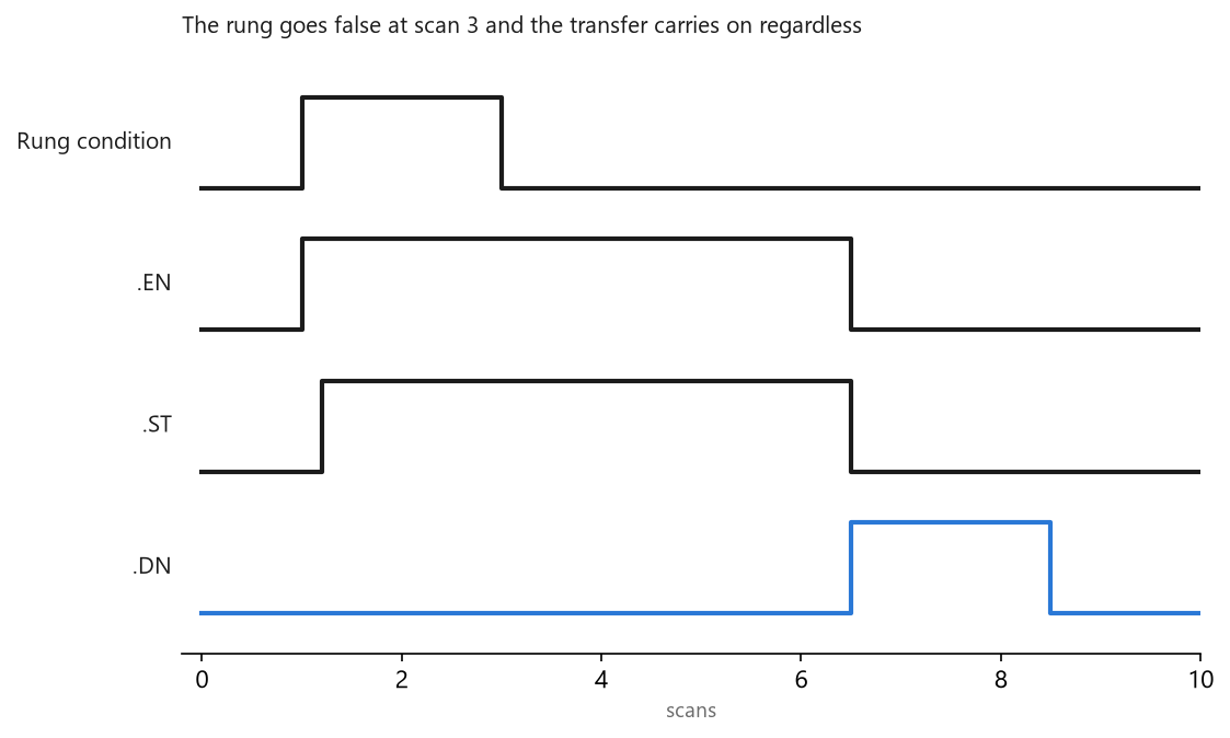
MSG is a transitional instruction. The manual’s instruction is exact: in ladder logic, insert an instruction to toggle the rung-condition-in from false to true each time the instruction should execute. In Structured Text, insert a condition so it executes only on a transition.
A one-shot, in other words. A MSG on a plain XIC fires as fast as the scan allows and fills the message queue with copies of itself.
What happens when the rung goes false mid-transfer surprises people, so here it is from the manual: the enable bit is set when EnableIn goes true and stays set until either .DN or .ER is set and EnableIn is false. If EnableIn goes false while .DN and .ER are both clear, .EN stays set. The transfer is asynchronous to the scan and it does not abandon itself because your rung changed its mind. So the rung precondition Rockwell recommends in its own Module Reconfigure example is an XIO of the MSG’s own .EN bit, in series, which keeps you from re-triggering something that is still in flight. Two hard rules go with the control tag on top of that, and both are printed in the guidelines table: each MSG instruction requires its own control tag, data type MESSAGE, controller scope, and the tag cannot be part of an array or of a user-defined data type. That last clause stops a lot of clever designs before they start — no array of MESSAGE tags indexed by a device number, no MESSAGE member tucked inside the UDT that describes a piece of equipment. And the warning printed in bold above the member list deserves reading twice: do not change .DN, .EN, .ER, .EW or .ST, either individually or through the .FLAGS word, because the controller may take a non-recoverable fault and clear the project from its memory when it does.
Source and destination data both have to be controller-scoped as well. A MSG can only access tags in the Controller Tags folder.
Cache, buffers, and the number 16
Tick Cache Connections and the connection stays open after the message completes, which the manual says optimises execution time because opening a connection on every execution costs you. Leave it clear and the connection closes and frees up for something else.
The limits are per controller family and they are not close to each other.
| Controller | Connections you can cache |
|---|---|
| CompactLogix 5370 or ControlLogix 5570 | Up to 32 |
| ControlLogix 5580 | Up to 256 |
There is a second number that gets confused with the first and should not be. On a CompactLogix 5370 or ControlLogix 5570, enabling more than 16 MSGs at one time means some of them may be delayed entering the queue; on a ControlLogix 5580 the same warning applies past 256. That is a limit on how many are in flight, not on how many are cached, and the fix Rockwell offers is a management strategy — enable them in sequence, enable them in groups, or write logic to coordinate them. A rung of sixteen MSGs all conditioned on the same 1-second bit is the pattern that trips it.
Then the unconnected buffers, which are a third thing again. A CompactLogix 5370 or ControlLogix 5570 can have 10 to 40 of them and defaults to 10. If every buffer is in use when an instruction leaves the message queue, that instruction errors and does not transfer its data — it does not wait, it fails. Keep the number of unconnected and uncached MSGs below the number of buffers, or raise the buffers toward 40.
Cache the ones that run constantly. Leave the occasional ones uncached. And if a single MSG round-robins its path across a dozen devices, Rockwell’s own guidance in 1756-PM012 is to clear the cache box for it, because the path changes every time and caching a connection you are about to abandon buys nothing.
When nothing has come back at all
The timeouts are longer than people expect, which is why a broken MSG can look like a hung MSG.
.UnconnectedTimeout defaults to 30 seconds and covers both an unconnected message and the act of making a connection. For an already-connected message the timeout is built from two members: .ConnectionRate defaults to 7.5 seconds and .TimeoutMultiplier defaults to 0, which means a factor of 4, so 7.5 × 4 is the same 30 seconds. Rockwell’s instruction if you want to change it is to adjust ConnectionRate and leave the multiplier alone.
Thirty seconds of a rung looking busy and nothing else happening.
What to check next
Put .ERR and .EXERR on a watch list before you change anything, and set the display format to Hex on both.
Every table in the manual is in hex, and comparing a decimal 4 against a documented 0004 has cost people real time. If .ERR reads 0001 and .EXERR reads 0204, the request left and nothing answered, so the question is now about the path and the far end rather than about the message: browse the path again from the tree, then confirm the far controller is powered, in Run, and reachable from that bridge card.
If it is 00FF with 210B, it is the tag name, and nothing else. Go and read it off the remote controller’s tag editor rather than off the drawing.
For everything hanging off the same bridge that is competing for those connections, the arithmetic is in EtherNet/IP setup, RPI and faults and connection parameters and RPI.