The warper on this line runs 800 m/min with 640 ends in the creel, and a broken end has to stop the beam on a 1.2 s drive ramp that still leaves about 8 m of warp running on past the break. What plc textile machinery needs from the controller follows from numbers like those: a clean speed reference chain, tension loops that do not fight each other, a stop sequence that leaves the broken end where the operator can find it, and a recipe per article. Here is how those four are built on the two stacks you meet most, S7-1500 with SINAMICS and CompactLogix with PowerFlex.
The example line is a direct warper feeding a sizing machine, with a stenter in finishing; all numbers are this line’s.
What you need before you touch a drive parameter
| Item | Siemens stack | Rockwell stack |
|---|---|---|
| Controller | S7-1516-3 PN/DP, TIA Portal V17, 4 ms cyclic interrupt for the reference chain | CompactLogix 5380, Studio 5000 v33, 4 ms periodic task |
| Section drives | SINAMICS S120 on the warper and sizing sections, G120 on fans and pumps | PowerFlex 755 on the sections, PowerFlex 525 on auxiliaries |
| Network | PROFINET, PROFIdrive telegram 1 or 3 per axis | EtherNet/IP, drive add-on profile, 4 ms RPI on the sections |
| Speed feedback | Encoder on a measuring roller for true fabric speed | Same, into a high speed counter module or the drive encoder option |
| Tension feedback | Load cell roller with an amplifier to a 4-20 mA input, or a dancer with a potentiometer | Same |
| Yarn break | Electronic stop-motion sensors, one per end, wired to distributed I/O on the creel | Same, POINT I/O on the creel |
| Safety | EN ISO 11111 for the machine, safety controller for the guards and the stop | S7-1500F or Compact GuardLogix |
Two facts shape the design: fabric speed comes from a measuring roller, never from a driven roller, and the master reference lives in the PLC, not in a drive.
Build the reference chain: line speed times draw ratio
Every section receives the master line speed in m/min multiplied by its draw ratio, then converted to the drive’s units. On the sizing machine the draw between the size box and the drying cylinders is 1.005 on this article, half a percent of wet stretch, and between the cylinders and the headstock 1.002. The ratios are recipe values; a polyester filament warp and a cotton spun warp do not tolerate the same stretch.
A section with a dancer adds a trim on top of the ratio. The dancer sits mid-stroke at 50 percent when the section is matched; if it drops, there is slack and the downstream section speeds up a little. Here is the block for one section in SCL, called from the 4 ms cyclic interrupt.
// FB_SectionRef, SCL, TIA Portal V17, S7-1516-3 PN/DP, called every 4 ms from OB35
// Line_Ref in m/min from the master, Dancer_Pos 0..100 percent, 50 = mid stroke
// Trim authority is +/- 3 percent of the section reference

#Err := 50.0 - #Dancer_Pos;                              // positive when the dancer drops
#Integ := #Integ + #Err * #Ki * 0.004;                   // 4 ms sample time
#Integ := LIMIT(MN := -3.0, IN := #Integ, MX := 3.0);
#Trim := #Err * #Kp + #Integ;
#Trim := LIMIT(MN := -3.0, IN := #Trim, MX := 3.0);

IF NOT #Line_Run OR #Break_Latched THEN
    #Integ := 0.0;                                        // no windup while stopped
    #Trim := 0.0;
END_IF;

#Section_Ref := #Line_Ref * #Draw_Ratio * (1.0 + #Trim / 100.0);

// PROFIdrive telegram 1: 16384 in NSOLL_A equals p2000 reference speed
#Roller_rpm := #Section_Ref / (3.14159 * #Roller_Dia_m);
#NSOLL_A := REAL_TO_INT(#Roller_rpm * #Gear_Ratio / #p2000_rpm * 16384.0);
The LIMIT on the integrator is the line that saves the restart. Without it the dancer sits on its stop for the whole break repair, the integrator climbs to its clamp and the section jumps 3 percent on the first metre. The 3 percent authority is deliberately small; if the dancer needs more, the draw ratio is wrong and the trim is hiding it. A load cell loop replaces the dancer position with tension in N and the same block applies, with a much lower integrator gain because a load cell has no storage to absorb an error.
On the Rockwell stack the same block is Logix ST with IF clamps instead of LIMIT, and the result goes into the PowerFlex 755 speed reference through the add-on profile’s output assembly. Adding the drive to the project is in how to add a PowerFlex AC drive to a Studio 5000 project, and drive selection and control modes in PLC motor control and drive systems.
Stop the line when an end breaks, and leave the end findable
The warper on this line runs 800 m/min with 640 ends in the creel. Each end passes a stop-motion sensor; a break drops the sensor and the PLC has to stop the beam before the broken end is wound under the sheet. On this warper the drive decelerates in 1.2 s, and the encoder count says about 8 m of warp runs on after the break, which the operator uses to find the end.
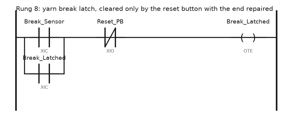
Rung 8 is a plain seal-in, cleared by the reset button. Press reset with the end still broken and the coil drops for as long as the button is held, then latches again on release; the run rung also examines Break_Sensor off, so a held reset cannot restart the beam. Break_Sensor here is the OR of the creel inputs after a 20 ms debounce; the section and end that dropped are captured separately so the HMI can point at the creel position.
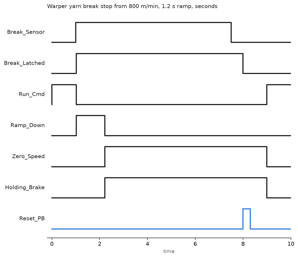
- Break at 1.0 s. The sensor input goes true. A 20 ms debounce in a 4 ms task filters the flicker from a loose end that has not broken.
- Latch at 1.02 s.
Break_Latchedsets,Run_Cmddrops, and the PLC stores the beam length counter and the creel position for the HMI. - Ramp down, 1.02 s to 2.22 s. The PLC clears the run bit in the control word and the drive decelerates on its own ramp-down time, 1.2 s on this warper, into an Active Line Module that returns the beam’s energy to the mains. Set the ramp shorter than the line module can absorb and the drive trips on DC link overvoltage.
- Zero speed at 2.22 s. The drive reports speed below threshold, the holding brake applies, and the screen shows the end number and the run-on.
- Repair and reset. The operator re-threads the end and the sensor clears at 7.5 s. The reset is pressed at 8.0 s, the latch clears at once, and the line restarts at 9.0 s on a slow crawl before returning to the recipe speed.
The reset is a momentary button; held longer than 5 s it raises an HMI alarm, because a stuck reset stops the rung from ever latching. The stop function itself sits in the safety controller under EN ISO 11111; the sequence above is the production stop on top of it. Interlock structure is in implementing PLC safety interlock systems.
Control the stenter chambers and the overfeed
A stenter is a chain that carries the fabric by its selvedges through heated chambers, 8 on this machine, each with a gas burner and a circulation fan. Each chamber is one PID on chamber air temperature, 120 to 190 C depending on the article, driving a modulating gas valve; the fan and the exhaust damper are recipe values rather than loops. The chain speed is the master reference, the fabric is fed onto the chain faster than the chain runs by the overfeed percentage, 4 percent on the article in the example, and the chain rails set the width through two positioning motors with encoders. Exit moisture from a sensor at the delivery end trims the chain speed within a recipe band, so a wet batch slows the machine rather than leaving damp fabric. PID mechanics for the chambers are in implementing PID control in PLC systems.
Keep one recipe per article
Every tension setpoint, draw ratio, chamber temperature, overfeed and width above is a recipe field, stored on the HMI or in a PLC data block and downloaded on article change. The recipe on this line is 46 values. Two rules that survive audits: an operator change to a running value is logged and does not overwrite the recipe until a supervisor saves it, and a recipe download is refused while the line runs. The structure follows the batch recipe pattern in PLC batch process control.
Decide what to keep on a retrofit
Old textile machines have good iron and bad electrics. On a 1990s sizing machine the DC drives, the tacho generators and the relay logic fail; the frames, the cylinders and the gearing are fine. The pattern that works is to replace the DC drives and motors with SINAMICS S120 or PowerFlex 755 and AC motors, or keep sound DC motors on a SINAMICS DCM or PowerFlex DC, fit an encoder on the measuring roller, move the creel sensors to distributed I/O, and rebuild the reference chain in the PLC. What you cannot skip is safety: the guards, the stop categories and the creel access must be brought to the current EN ISO 11111 requirements, and that survey often costs more than the drives.
Field notes
Dancer integrator wound up during a repair. A sizing section jumped at every restart after a break. The trim integrator had no clamp and no reset while stopped; the LIMIT and the reset in the block above were the whole fix.
Speed drift from a worn driven roller. The draw between size box and cylinders crept up over a year and the warp came off the beam overstretched. Fabric speed had been calculated from the driven roller’s rpm, and the roller had worn 0.4 mm on its diameter. A measuring roller with an encoder feeding the reference block ended the drift.
False breaks from a dirty creel. A warper stopped forty times a shift on ends that had not broken. Fly on the stop-motion sensors made them flicker. The 20 ms debounce and a monthly cleaning brought it to two or three real stops.
Frequently asked questions
Dancer or load cell?
A dancer where the material stretches and you have the space. A load cell where the web is stiff or the machine is compact.
Do I need PROFINET IRT or CIP Motion for a line like this?
Not for speed following. A 4 ms cyclic reference over PROFINET RT or EtherNet/IP with a 4 ms RPI holds the draw within what the fabric can show. Save IRT and CIP Motion for axes that must interpolate, and a textile line has few.
Where does the master speed reference live?
In the PLC, as one tag. A drive-to-drive master works until the master drive trips and every section loses its reference at once.
Next step
Trend every section’s reference and actual speed together with the dancer position in one chart; the setup is in PLC trend chart settings and monitoring. A draw problem shows there as a dancer creeping away from 50 percent long before the fabric shows it.