The seal on a wellhead shutdown rung belongs on the manual reset push button and nowhere else, so that a fusible plug which melts in a flare fire and later cools cannot re-energise the solenoid and reopen the SDV on an empty pad. That habit comes from the upstream half of this job, where the controller is an Emerson ROC809 on a solar panel at the end of a dirt road, talking over a radio that works most days. Downstream you have a tank farm with a control room, a fibre ring and a custody meter whose numbers end up on an invoice. The habits that keep you out of trouble in one place get you into trouble in the other.
Pick the box for the wellpad, not for the office
| Controller | Where it fits | Points worth knowing |
|---|---|---|
| Emerson ROC809 | Gas wells, plunger lift, flow measurement on board | AGA-3 and AGA-7 calculations built in, a couple of watts for the bare CPU |
| Schneider SCADAPack 470i | Multi-well pads with mixed I/O | Serial ports for a radio, dual Ethernet, DNP3 outstation with event buffering |
| ControlLogix 1756-L83E | Central facility, compressor station, LACT skid | Full Studio 5000 toolset, needs mains power and a heated cabinet |
| CompactLogix 5069-L306ER | Small pad with a proper power supply | Cheaper than ControlLogix, still wants tens of watts with its I/O and conditioned space |
The power budget decides this more often than the I/O count. A wellpad on solar gets a 100 W panel and a 200 Ah battery for five days of autonomy at high latitude. A controller drawing 25 W eats 600 Wh per day and fails in the first week of December. A ROC809 with its radio duty cycled sits under 5 W average on pads I have metered, and survives.
Temperature is the other filter. Most standard Logix hardware is rated 0 to 60 C. At minus 35 C in January the LCD is dead and the electrolytic capacitors are outside their rating, so either buy extended temperature hardware or heat the cabinet with a thermostatically switched 60 W heater and accept the parasitic load. Class I Division 2 certification applies to the enclosure and the wiring method, not just the controller.
Write the ESD rung so it cannot restart the well on its own
Wellhead shutdown follows API RP 14C. Pressure sensors on the flowline, a fusible loop for fire, and a hydraulic supply that bleeds to close the surface safety valve. The PLC has one job in that chain: it holds the solenoid energised only while every permissive is true.
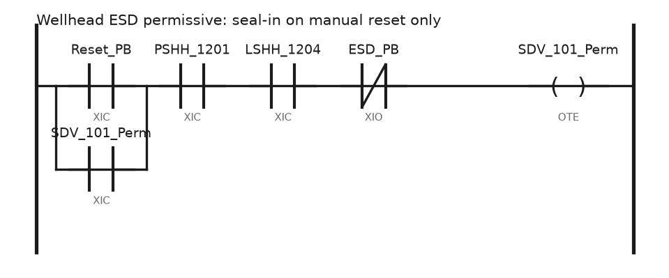
Rung 3 (WellPad_ESD, 100 ms periodic task):

  ---] [-----------] [------------] [-----------]/[--------( )---
   Reset_PB       PSHH_1201      LSHH_1204      ESD_PB     SDV_101_Perm
   |
   ---] [---
   SDV_101_Perm

Rung 4:
  ---] [-----------[TON Timer=Perm_Delay Preset=3000]---------------
   SDV_101_Perm

Rung 5:
  ---] [-----------------------------------------( )---
   Perm_Delay.DN                                SOL_101_Energise
PSHH_1201 and LSHH_1204 are wired normally closed on healthy, so the XIC is true while the flowline pressure and the separator level are in range. Three details make this different from a motor seal-in.
- The seal is on the reset push button only. Lose power, lose the seal, and the well stays shut in until someone presses reset on the pad. Nothing in the logic restarts a well.
ESD_PBis examined as a normally closed input. A cut wire to the emergency stop trips the well instead of arming it.- The 3 second delay before energising the solenoid gives the hydraulic power unit time to build pressure. Without it the HPU starts against a solenoid that is already calling for flow, and the valve creeps open at 40 bar instead of snapping open at 140 bar.
Keep the first-out cause: when the permissive drops, latch which contact opened first into a retentive tag and timestamp it with the controller wall clock. A pad that shuts in at 03:40 with no first-out record turns into a day of arguing with the production team. The wider interlock pattern is in implementing PLC safety interlock systems.
Budget the poll cycle before you blame the radio
Twelve wells on a 900 MHz licensed radio at 9600 bps is a real constraint. The arithmetic is short.
| Item | Value |
|---|---|
| Read of 40 holding registers, request | 8 bytes, 8 ms on air |
| Response, 40 registers | 85 bytes, 88 ms on air |
| Radio key-up and squelch settle | 60 to 120 ms each direction |
| Master turnaround delay | 50 ms |
| Practical time per well | 350 to 400 ms |
| Full cycle, 12 wells, no retries | 4.5 s |
One dead site with a 3 second timeout and three attempts adds 9 seconds to that cycle, so the scan goes from 4.5 to 13.5 seconds and the whole field looks slow. Set the timeout to four times the measured response, not a round number, and move a dead site to a slow retry list after three consecutive failures.
On cellular, stop polling and switch to DNP3 unsolicited reporting. Put analog inputs in Class 2 with a deadband, binary changes in Class 1, and run an integrity poll every 15 minutes to resynchronise. A pad that reports a 0.5 bar pressure change instead of sending 40 registers every 10 seconds uses a tenth of the data allowance and tells you sooner about what you actually care about. Protocol selection and register mapping are in PLC communication protocols for SCADA.
Leave custody transfer to the flow computer
The LACT skid or the gas meter run has a flow computer for a reason. A FloBoss S600 or an ROC with AGA firmware holds the audit trail, the meter factor and the configuration change log the measurement auditor will ask for. Do not reimplement AGA-3 in ladder because it looks like a few multiplications.
What the PLC does instead:
- Read the flow computer over Modbus as an outstation. Totals, flow rate, temperature, pressure, alarm status.
- Handle 32-bit values as register pairs and confirm the word order on the bench. An ROC sends floats in a different word order from a ControlLogix
COPinto a REAL, and that mismatch produces numbers like 1.7e38 rather than 143.2. - Read the non-resettable total, not the resettable one, and calculate the delta in the PLC. A resettable total zeroed by a technician makes a negative hour in the historian.
- Run the skid sequencing: pump start, divert valve on a bad sample, proving sequence permissives, and the alarm when the meter factor drifts more than 0.25 percent between provings.
Control tank farm level with two independent paths
API 2350 asks for an overfill protection layer independent of the inventory gauging. In practice that means two devices and two wiring paths.
- Inventory gauge: guided wave radar or a servo gauge, 4-20 mA with HART, into the PLC analog card. This is the number the terminal bills on.
- Overfill: a separate high high level switch, usually a vibrating fork or a float, hardwired to a digital input and to the ROSOV solenoid circuit.
- Fill rate limit: hold the inlet below 1 m/s linear velocity until the inlet nozzle is submerged, to keep static generation down on light products.
- Valve sequencing: open the destination valve fully before the pump starts, and prove it with limit switch feedback rather than command feedback. A pump started against a closed motor operated valve on a 12 inch line is a pipeline rupture, not a nuisance trip.
- Grade the alarms: high at 90 percent, pre-alarm with calculated time to overfill at 95 percent, high high hardwired at 98 percent. The time to overfill figure, worked out from level rate of change, is the one operators actually use.
Field notes
The radio poll storm. A new pad went in behind a hill and could hear the master but not the neighbouring outstation. Classic hidden node. Both stations transmitted over each other and the whole field started retrying. Receive signal strength at the master looked fine at minus 82 dBm, which is why it took two days to find. The fix was a 3 m mast extension and a repeater path, plus staggered poll slots.
The well that restarted itself. An early version of the rung above used a latch driven by the healthy bits rather than a sealed reset. After a fusible plug melted in a small flare fire, the plug cooled, the pressure switch reset, and the logic re-energised the solenoid and reopened the SDV with nobody on site. That is why the seal sits on the manual reset and nowhere else.
Modbus floats that read as nonsense. A SCADAPack was mapped to a ControlLogix over Modbus TCP. Flow read 1.7e38 on half the registers. The SCADAPack sent the low word first, the Logix message assumed the high word first. A SWPB on the DINT before the COP to REAL fixed every tag at once. Always prove a known value, like a static temperature, before you trust the map.
The radar gauge that froze. A stilling well on a gasoil tank built up a wax collar near the top. The guided wave radar locked onto the collar and reported a constant 4.1 m while the tank kept filling. The independent fork switch stopped the transfer at 98 percent. A frozen value alarm, no change greater than 5 mm in 20 minutes while the inlet valve is open and the pump runs, now catches it.
Frequently asked questions
RTU or PLC for a wellpad?
The labels blur. Choose on power draw, temperature rating, protocol support and event buffering. If the site has to hold 4000 timestamped events through a two day radio outage, you want an outstation with proper DNP3 event queues, not a general purpose PLC with a Modbus map.
Where should the shutdown logic live on a remote pad?
At the pad. The local controller shuts the well in on its own inputs. SCADA can request a shutdown, but it must never be the only path, because the link will be down on the night you need it.
How do I get historical data back after a comms outage?
Buffer at the outstation with timestamps and upload on reconnect. DNP3 does this by design. On Modbus you build it yourself with a file style register block and a read pointer, one more argument for DNP3 on cellular sites.
Do I need a separate SIS on a wellpad?
Usually not. The API RP 14C safety functions are mostly hardwired pilot and pneumatic devices, with the controller as a permissive. A gas plant or compressor station with SIL rated functions is a different question and gets a rated safety controller.
Next step
Get the link and the alarm path right before adding features; everything above depends on knowing the state of a site you cannot see. Remote monitoring and control of PLC systems covers the data path and stale value handling, and what is SCADA sets out how the field data reaches the person on call.