SWPB and Byte Order: The Day It Bites on a Modbus Register
Two holding registers come back from a power meter as 16#43CF and 16#999A, a COP lands them in a REAL, and the line voltage on the screen reads -1.5951E-23. The meter is fine, the wiring is fine, and all four bytes arrived in the order the meter sent them.
The swap happened inside your own controller.
Logix takes the first INT of a two-element pair as the lower sixteen bits of a DINT — 1756-RM018A states that on page 286, in the worked example for turning a pair of INTs into one value — while Modbus puts the most significant part first on the wire. Copy one straight into the other and the two halves land the wrong way round every single time. SWPB is the one-instruction fix, and its three order modes exist because there are exactly three ways four bytes can come out rearranged.
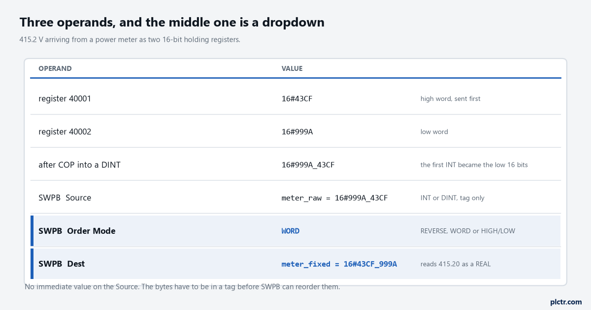
Every value in this table is correct at the point it is measured. The only thing that is wrong is the assumption that a copy preserves order across a change of data type.
What the protocol fixes, and what it leaves to the vendor
Modbus settles the byte order inside a register and says nothing useful about the order of registers.
The clearest statement of it in Rockwell’s own literature is in the Micro800 general instructions manual, 2080-UM002S, under Endian Configuration: the Modbus protocol is big-endian in that the most significant byte of a 16-bit word is transmitted first, and for data types larger than 16 bits — DINT, LINT, REAL, LREAL — multiple Modbus addresses may be required, but the most significant byte is always the first. That is the contract. Inside one register you know where the two bytes go; across two registers you know which one carries the top half, and a device that honours the specification sends the high word first. What the specification never promised is that your controller assembles them in that order, and that is where the trouble starts.
Now the part that makes this argument unwinnable in a meeting.
Rockwell’s 2004 application solution for running Logix controllers on Modbus, CIG-AP129A, describes the conversion it performs in exactly the opposite vocabulary: it converts data from the format used on Modbus, which it calls little endian, to the format used with Logix5000 controllers, which it calls big endian. Two publications from the same vendor, twenty-two years apart, using the two words in opposite directions — and both of them are describing behaviour that works. The practical conclusion is not that one is wrong. It is that “endian” is the wrong unit of discussion at a panel: write down which byte of the value arrives in which register, and which end of the destination tag it lands in, and the argument disappears.
Two manuals, two opposite labels for the same behaviour, and both of them ship working code.
The three order modes, and which one is yours
The order mode table is four lines and it is the whole instruction.
An INT source has only one possible swap, AB to BA, so any order mode does the same thing to it. A DINT source has three: ABCD to DCBA is REVERSE, ABCD to CDAB is WORD, and ABCD to BADC is HIGH/LOW. Those map cleanly onto the three failure modes. WORD is the one you want when the two registers landed in the wrong order and the bytes inside each are right, which is the case a plain COP produces every time on a conformant device. HIGH/LOW is for a device that reverses the bytes inside each register while sending the words in the right order. REVERSE is for one that does both, which is what you get from a slave built on a little-endian microcontroller with no conversion layer at all.
One dropdown, three settings, and only one of them is right for your device.
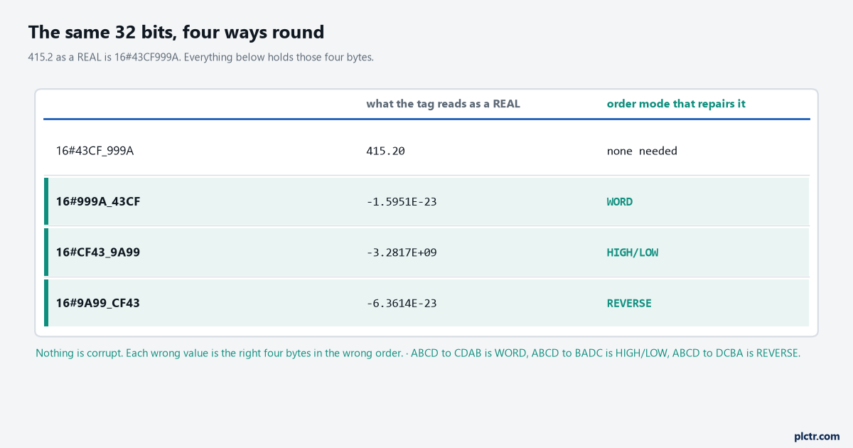
415.2 volts is 16#43CF999A. The other three rows contain those same four bytes and read as numbers with no physical meaning whatsoever, which is the useful part — a byte-order fault never looks like a small error.
A reading that is out by a factor of ten is a scaling problem to chase.
A reading of -1.5951E-23 where volts belong is bytes in the wrong order, and the moment you recognise that shape you can stop looking at the CT ratio, the transformer and the register address.
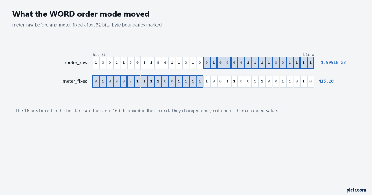
The boxed sixteen bits are the same sixteen bits in both lanes. They changed ends; not one of them changed value.
Three rungs from a Modbus buffer to a number an operator can read
The sequence is COP, SWPB, COP, and each one is doing something specific.
The first COP takes the pair of INTs out of the buffer and puts them in a DINT, and the Length operand is the part people get wrong — the manual’s own example spells it out, Length 1 means one times the number of bytes in the destination data type, so a Length of 1 into a DINT copies four bytes and consumes two INTs. The SWPB then reorders those four bytes into a second DINT. The last COP reinterprets that DINT as a REAL without converting anything, which is the entire reason a copy is used rather than a move: a MOV from a DINT to a REAL would convert 1,137,678,746 into the floating-point number 1137678784.0, and a COP leaves the bits alone so they can be read as 415.2. The element-and-byte arithmetic that decides all three Length operands is worked through in moving a recipe into the PLC with UDTs, arrays and the copy that breaks.
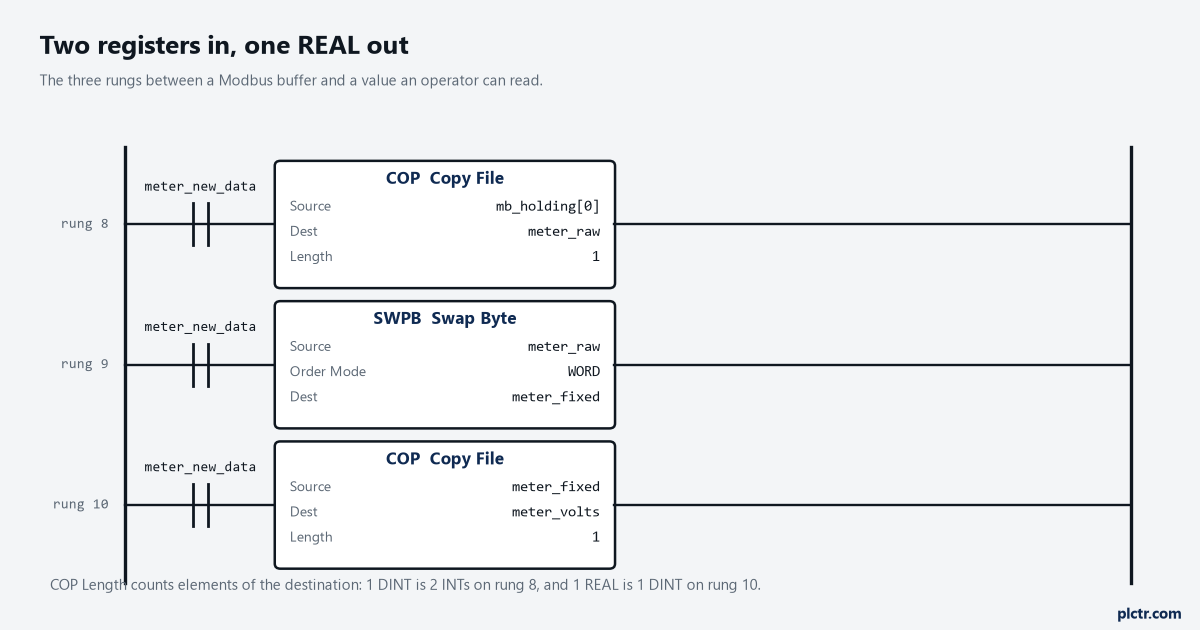
Three rungs and one dropdown. Changing the order mode is the only edit needed if the meter is replaced by one that packs its words the other way.
SWPB will not take the REAL directly, and this is where the reference contradicts itself in a way worth knowing about. The summary table at the front of the Move/Logical chapter says SWPB rearranges the bytes of an INT, DINT or REAL tag. The operand table on the instruction’s own page offers INT and DINT and nothing else. Trust the operand table, do the swap while the value is still a DINT, and treat that chapter summary as the reason somebody on your team will insist it should work on a REAL.
The sign extension waiting for an INT source
There is one line in the Dest table that will reproduce the original problem in a new place.
If the source is an INT and the destination is a DINT, the result is sign extended after the bytes are swapped. So a status register of 16#F0A1, swapped to 16#A1F0 and written into a DINT, arrives as 16#FFFF_A1F0 rather than 16#0000_A1F0, because bit 15 of the swapped value is set and the promotion carries it upward through sixteen more bits. For a signed measurement that is correct and welcome. For a register that is a bit pattern, or for the low half of a 32-bit value you are about to assemble by hand, it is a silent corruption of everything above bit 15. Keep the destination an INT when the source is an INT, and assemble the 32-bit value with a COP afterwards.
Sign extension is the right answer to a question nobody asked here.
What SWPB will not do
Four restrictions, and each one changes how the rest of the logic has to be built.
The source must be a tag: there is no immediate operand, so you cannot swap a constant, and anything arriving from a message has to land in a tag first anyway. There is no function block version — the instruction is available in ladder and in structured text only, where it is written SWPB(Source, Order Mode, Dest) and the HIGH/LOW mode is typed as HIGHLOW without the slash. It affects no math status flags at all, which means a swap can never be the thing that set S:V two rungs later. And it handles one tag per execution, so an array of readings needs one instruction per element or a loop — the manual’s own structured text example uses SIZE to find the length and a REPEAT loop to walk it, which is the pattern to copy when a meter hands you sixty registers at a time and is covered in the language terms of structured text for people who write ladder.
Finding the right mode without guessing at it
Do not try all four and keep the one that looks plausible. Find a register whose value you already know.
Every meter has one to offer.
A firmware revision, a serial number printed on the front, a configured CT ratio, a demand window you set yourself, or a frequency that will read 50.00 or 60.00 to two decimals and nothing else. Read that register, assemble it the way your logic assembles the others, and compare the four possible byte orders against the number you can see on the device’s own display. Whichever order produces it is the order for every 32-bit value in that map, and you only have to do this once per device type. The same discipline applies one layer up to the addresses themselves, where an off-by-one on the register number produces a value that is wrong in a much more believable way — that is the subject of Modbus TCP from a Raspberry Pi and why your value is one address out.
What to check next
Write the byte order into the register map document, in the same table as the addresses, using the four-letter notation the SWPB dropdown uses. “40001-40002, REAL, volts L-L, WORD” is a complete instruction to the next person and “big endian” is not. Then check the sign on every 16-bit register in the map before you assume any of them need swapping at all, because a single INT register that reads -1 where 65535 belongs is a data-type problem rather than an order problem. If the connection itself is the part you are still building, the function codes and the register-map arithmetic are in reading a Modbus RTU power meter from a PLC, and the frame-level view of doing this over Ethernet — including where the byte order shows up in the socket data — is in Modbus TCP from a 1756-EN2T with the socket object.