BTD: Pulling a Field of Bits Out of One Word and Into Another
The status DINT coming back from the bench scale reads 306,997. The weight is 1,199, and the rest of that number is a units code, a stable flag and a sequence counter, packed into the same word because the vendor had thirty-two bits and saw no reason to waste them.
BTD is the instruction that unpacks it, and the whole instruction is five operands.
Tell it where the field starts in the source, how many bits wide it is, and which bit of the destination it should land on. It copies the group, shifts it into position, writes it into the destination and leaves every destination bit outside the field exactly as it was. The source is not modified. Three of the five operands are plain numbers typed straight onto the rung — and that last detail is the one that decides whether BTD fits your problem at all, because those three cannot be tags.
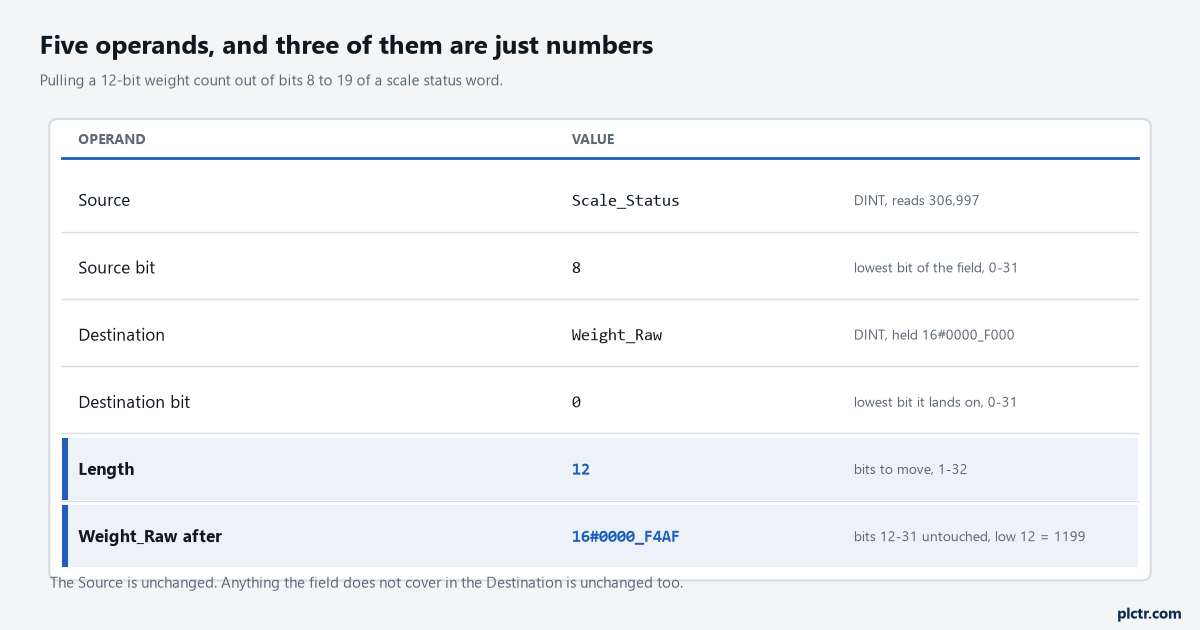
The Length operand is the one to write in the rung comment. Everything about whether this instruction is correct comes back to whether 12 is still 12 after the next firmware update on the scale.
Where the field starts, and where it lands
Two bit numbers and a count. That is the whole of it.
Source bit is the lowest bit number of the group in the source, and the manual is careful to say lowest rather than first, because the group runs upward from there. Destination bit is the lowest bit number the group lands on. Length is how many bits come across, valid 1 to 32, and both bit numbers are valid 0 to 31 with the additional requirement that they sit within the range of their own data type — bit 20 of an INT destination is not a legal operand, because an INT stops at bit 15. Work the scale example through once. Scale_Status holds 16#0004_AF35; bits 8 to 19 hold 16#4AF; source bit 8, destination bit 0, length 12; and Weight_Raw comes out with 16#4AF in its bottom twelve bits, which is the 1,199 the scale meant.
The scale’s own manual calls that field bits 8 to 19. Use its numbers, not yours.
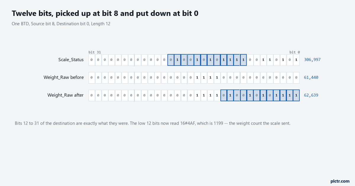
The destination started with rubbish in bits 12 to 15 and still has it afterwards. BTD writes the field and nothing else, which is a feature until the day it hides a value nobody cleared.
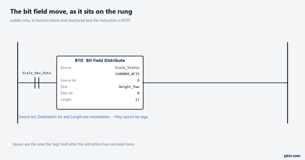
Source bit, destination bit and length are immediate values. There is no version of this rung where the field position comes from a tag.
What BTD does that MVM cannot
MVM and BTD look like the same instruction until you need the value to arrive somewhere else.
A masked move passes bits straight through: a mask of 16#000F_FF00 moves those twelve bits of the source into the same twelve bit positions of the destination, so the weight ends up sitting at bits 8 to 19 again and everything downstream of it has to divide by 256 to get a number it can compare. BTD shifts, and that is the entire difference between the two. If the field is already in the right place — a command word being assembled from bits that were always bits, a status word being copied with two bits protected — MVM is the simpler instruction with one fewer number to get wrong, and the way that plays out on a real drive word is covered in commanding a PowerFlex 525 from a ControlLogix. If the field has to move, BTD does it in one instruction and MVM cannot do it at all.
The third option is arithmetic, and it is not wrong.
A CPT expression of (Scale_Status AND 16#000F_FF00) / 256 produces the same 1,199, in one instruction, with the mask and the shift visible. What it costs you is that 256 — a magic number nobody will recognise as “bit 8” in two years, and the number that has to change when the vendor moves the field by one bit in a firmware revision. BTD spends three operands saying the same thing in the vocabulary the device’s manual uses. The fourth option, twelve rungs of XIC and OTE, works, executes in about the same time, and is twelve rungs.
One instruction, three numbers, and the vocabulary the device’s manual already uses.
The bits that fall off the end
Ask BTD to put twelve bits where only eight will fit and it does not complain.
The manual’s sentence is worth quoting because it settles two questions at once: if the length of the bit field extends beyond the destination, the instruction does not save the extra bits, and any extra bits do not wrap to the next word. No fault, no status flag, no truncation warning — the bits that did not fit are gone, and the next element of an array is not touched. Destination bit 24 with a length of 12 into a DINT keeps eight bits and drops four, every scan, quietly.
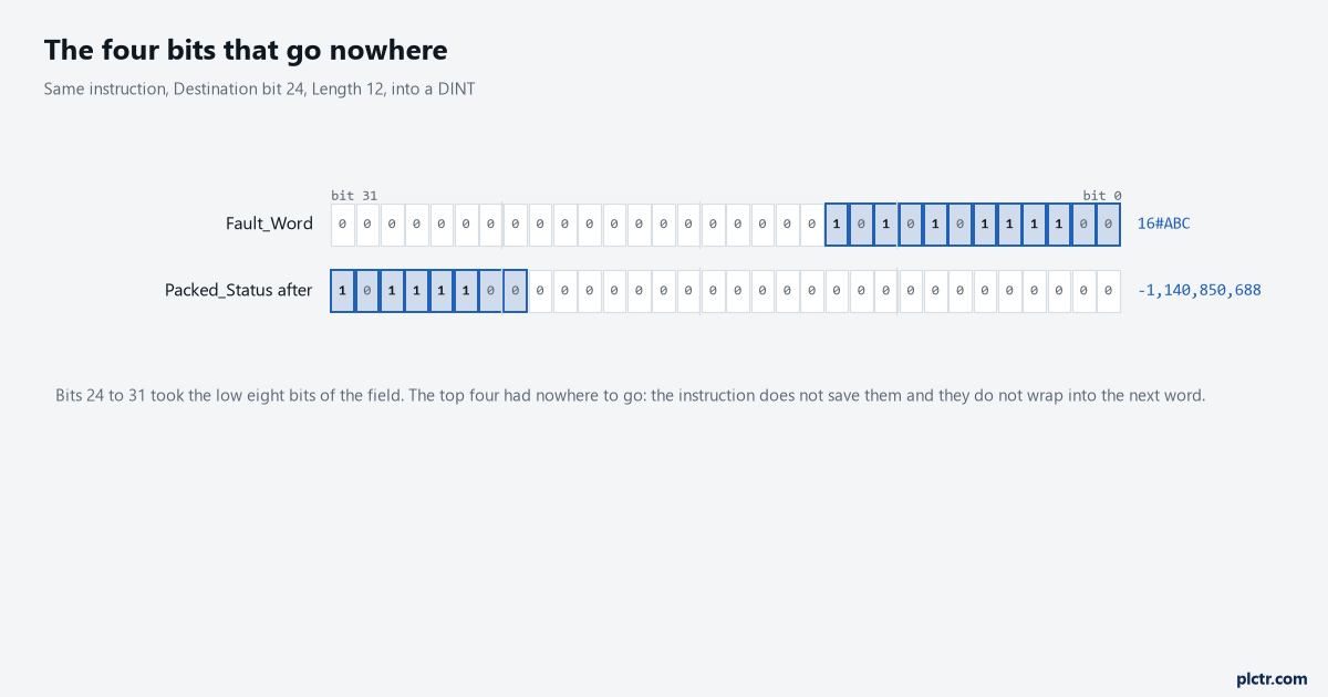
16#ABC went in and 16#BC arrived. The 16#A is not in the next word and it is not in a flag; it was simply not saved.
Destination bit 24 with a length of 12 leaves 16#BC00_0000 in the word, which a watch window will show you as -1,140,850,688.
Now the constraint that shapes designs rather than rungs.
Source bit, destination bit and length are immediates. They cannot be tags, they cannot be computed, and there is no indirect form of this instruction, so a field whose position is decided at runtime — a protocol where the offset comes in the header, a multiplexed status word where the meaning of bits 8 to 19 depends on a command code — cannot be handled by one BTD. What people do instead is one BTD per case behind its own comparison, which is honest and readable up to about six cases, or a shift-register approach where the data moves rather than the field, which is the pattern behind tracking a carton through four zones with a shift register.
Source and destination may be the same tag
The manual’s first BTD example does something that looks like a mistake and is not.
It names the same tag as source and destination, value_1, and moves bits within it — which is a shift inside a single word, expressed in bit numbers rather than as a multiply or a divide, and it is a legitimate use of the instruction. The thing to be careful about is overlap. Where the source field and the destination field cover some of the same bits of the same tag, the reference does not state the order in which the instruction reads and writes, so a field moving by fewer bits than its own length is a case worth staging through a scratch tag rather than assuming. And whether or not the fields overlap, you have overwritten the original: any other rung that was reading those bits of value_1 is now reading the shifted copy, on the same scan, with no warning.
Two rungs later is too late to discover that.
Zero-fill, and the INT that loses its sign on the way in
One line on the BTD page prevents a whole class of confusion: a SINT or INT tag is converted to a DINT value by zero-fill.
That is the right behaviour for a bit field and the wrong behaviour for a number, and knowing which one you are holding is the entire skill. An INT status word of 16#F0A1 arrives inside the instruction as 16#0000_F0A1, so bit 15 stays bit 15 and bits 16 to 31 are zero — exactly what you want when bits 12 to 15 are an alarm class. Had this been an ordinary move, the general rule in the common attributes chapter applies instead: logical instructions use zero fill, all other instructions use sign-extension, and the same 16#F0A1 would have arrived as 16#FFFF_F0A1. Same sixteen bits of input, two different thirty-two bit values, decided by which instruction you reached for. Register maps that hand you signed sixteen-bit values mixed with bit fields are the usual source of this, and the mapping side of it is worked through in reading a Modbus RTU power meter from a PLC.
A bit field is not a number, and the instruction you reach for decides which one you are holding.
In function block and structured text it is BTDT, and the Target changes the answer
BTD is a ladder instruction only, and the substitute is not a straight substitute.
BTDT takes one more input — Target — and the description says what it does with it: the instruction first copies the Target to the destination, then copies the specified bits from the source and writes them in. So the bits outside the field come from Target rather than from whatever the destination happened to hold, which turns a modify-in-place instruction into a build-a-new-word instruction. Wire Target to the destination tag and you have BTD’s behaviour back. Leave Target at its default and every bit outside the field is rewritten from it on every execution, which will look like something clearing your bits at random until you spot the pin. The structured text form is BTDT(BTDT_tag) with the operands assigned to the tag’s members first, in the style covered in structured text for people who write ladder, and BTDT affects the math status flags on a CompactLogix 5380, ControlLogix 5580 or ControlLogix 5590 while doing nothing to them on a 5370 or 5570.
What to check next
Get the field map out of the device’s manual in bit numbers before you write the rung, and write the three operands into the rung comment in the same words the manual used — “bits 8-19, weight count, unsigned” beats a comment that says “unpack scale data”. Then change the display style on the source tag to Binary and watch it while the process runs, because a field that is one bit out is invisible in decimal and obvious in binary. If the value only looks wrong at one end of the range, the field is not the problem and the sign is: check whether the device meant those twelve bits as signed, because BTD will hand you 4,095 where the device meant -1.