Removing an Axis From a Running Kinetix 5700 System Without Faulting the Rest
A 2198-D032-ERS4 is two axes behind one Ethernet connection on one set of bus bars, and inhibiting either half takes the other half with it. Getting the module off the rail is a different order of problem: control power and mains off, five minutes for the DC bus to discharge, a voltmeter on the terminals, and then a 55 mm hole in the middle of a cluster whose DC-bus links are all fixed lengths.
So there are two removals hiding inside the question, and only one of them happens with the line running. The logical removal — inhibit — does what people hope: the CIP connections to that drive shut down and connections and motion on every other drive carry on uninterrupted. The physical removal does not happen at all until the rail is dead.
The one that bites weeks later is neither. It is the number left behind in the project.
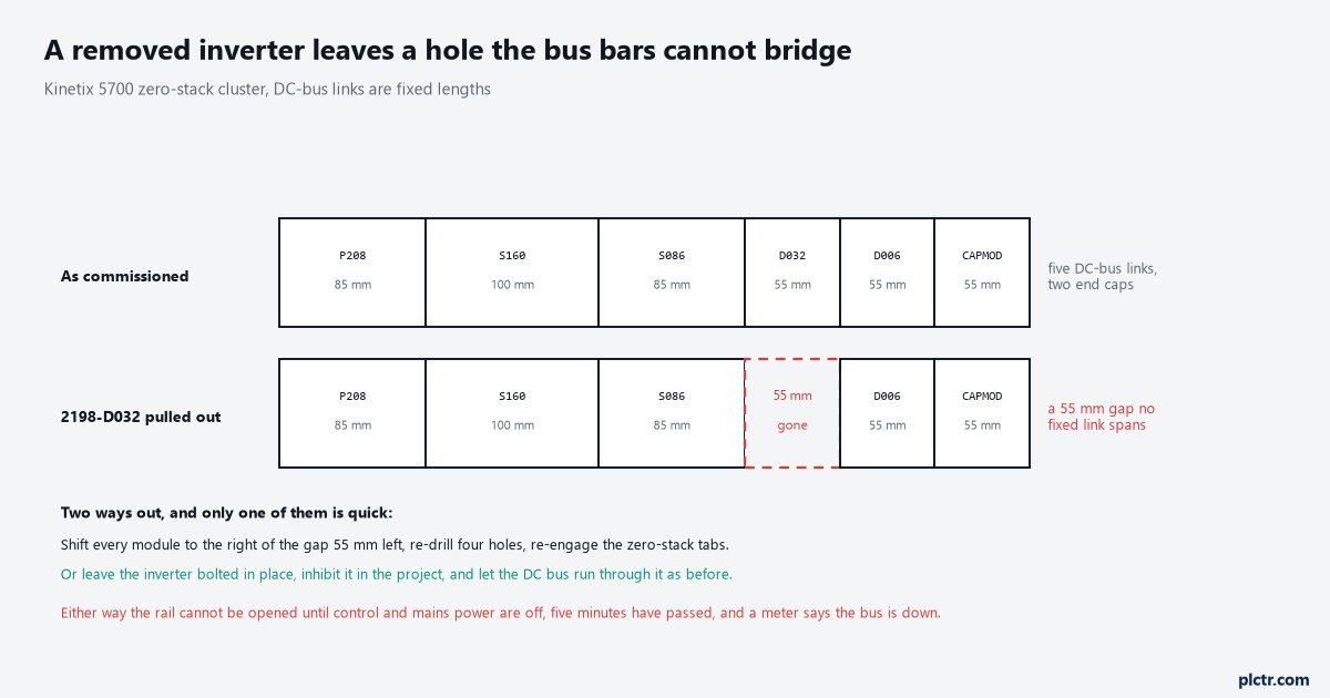
The gap is the part of this job that is not negotiable. DC-bus links come in fixed lengths and none of them spans a missing module.
What inhibit actually stops
Inhibit is the online move, and the manual is specific about what it costs.
Inhibiting an axis blocks the controller from using it, which is exactly what you want when the axis has faulted or the machine it drives has been taken out of service. The configuration manual states the result plainly: the CIP connections to the drive carrying the affected axis are shut down, and connections and motion on all other drive axes continue uninterrupted. There are three preconditions worth knowing before you write the rung. You can only inhibit an axis that has previously synched to the group — an axis that never synched cannot be inhibited at all. You stop all motion first and use MSF on the axes, because otherwise the axes turn themselves off when you inhibit or uninhibit one of them, which is a surprise on a vertical load. And inhibit or uninhibit of an axis also affects any half axes in the same drive, so Infeed_04A and Infeed_04B go down together whether or not you meant the second one.
Two axes, one module, one decision. That pairing is the single most common shock on a Kinetix 5700.
There is a coarser version of the same move that is often the right one. If you want every axis on a communication module out of service, the manual says it is more efficient to inhibit the communication module than to inhibit each axis in turn, and the controller restarts the connections automatically when you release it. The module-level inhibit lives on Module Properties under the Connection category as a checkbox, and it is the same checkbox the safety chapter tells you to tick before attempting a Reset Ownership, because an active connection makes the drive refuse.
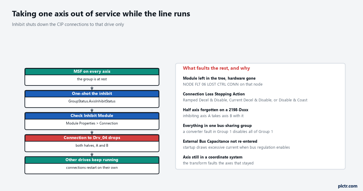
The left column is the procedure. The right column is what people actually ring up about.
What a wrong removal faults
Four failures, and none of them announces itself as “you removed an axis”.
The first is the module left in the tree after the hardware is gone. The controller keeps trying to open the connection, the drive is not there to answer, and you get the node faults for a lost controller connection: NODE FLT 06 LOST CTRL CONN, or NODE FLT 01 LATE CTRL UPDATE, and the manual notes that from firmware revision 11.001 other node faults can get there first. Because you cannot predict which one arrives first on a connection loss, the manual’s own recommendation is to leave the Connection Loss Stopping Action at its default of Current Decel & Disable and not to tune it — which is worth knowing if somebody has already set it to Disable & Coast to make a commissioning problem go away. That setting is the second failure in disguise. The Connection Loss Stopping Action fires on loss of the motion connection, and the manual’s examples of that loss are inhibiting the module and a network cable disconnect. So the tidy online inhibit you just performed is, from the drive’s point of view, the same event as somebody pulling the patch lead, and the motor stops the way that field says it will: Ramped Decel & Disable, Current Decel & Disable, or Disable & Coast. On a hanging load with no brake, Disable & Coast is a falling axis.
The third is the bus-sharing group, and it decides the blast radius of everything else.
Modules physically joined by one shared-bus connection system belong to one Bus Sharing Group in the project, and a converter that faults in Group 1 disables the Group 1 drives while Group 2 keeps running. A panel that was commissioned with every rail in Group 1 has no firebreak in it, and taking one inverter out of service is only ever as isolated as the group boundary allows. Up to 25 groups are possible; most projects use one because nobody revisited the question after the first download.
The fourth is the axis tag and everything that still points at it. Delete the axis from the project and every MAM, MAJ, MAG and coordinate-system reference that named it becomes an unresolved reference, and gearing that had it as a slave has nothing to drive. Cross-reference the tag before the delete, not after — finding every rung that writes a tag in Studio 5000 takes two minutes and saves the download that fails at five to six. Take the .ACD backup first as well; backing up a ControlLogix properly is the difference between undoing this and rebuilding it.
The bus calculation that changes, and the one that does not fix itself
Capacitance going down is harmless. The number in the project going stale is not.
Total system capacitance is the sum of the internal capacitance of every power supply, inverter, capacitor module and accessory module on the same DC-bus group, and it has to stay under the supply’s supported maximum — 13,000 µF for a 2198-P208. Take a 2198-D032-ERSx out and the total drops by 390 µF, which moves you further inside the limit rather than closer to it. The 24V control-power total drops by 1.7 A against its 40 A ceiling, the inrush total drops by 4.0 A, and the group’s summed motor power cable drops by whatever that axis was carrying, against the 1200 m CE and UK limit. All four of those numbers get better, and none of them needs an entry anywhere.
External bus capacitance does. It is the total system capacitance minus the supply’s own internal capacitance, it is typed by hand into the DC Bus page of a 2198-RPxxx regenerative bus supply, and the manual says an accurate value is required for proper operation. Nothing recalculates it when the hardware changes. Leave 2790 µF in a project whose rail is now worth 2400 µF and the symptom is not a fault code, it is behaviour: the regenerative bus supply’s troubleshooting table lists an incorrectly entered external bus capacitance under two separate conditions, DC-bus voltage fluctuations and excessive current drawn from the AC input when DC-bus voltage regulation is enabled. Both of those read like a supply problem and get chased as one.
Retype it. It is one field and it is the only field a removal actually requires.
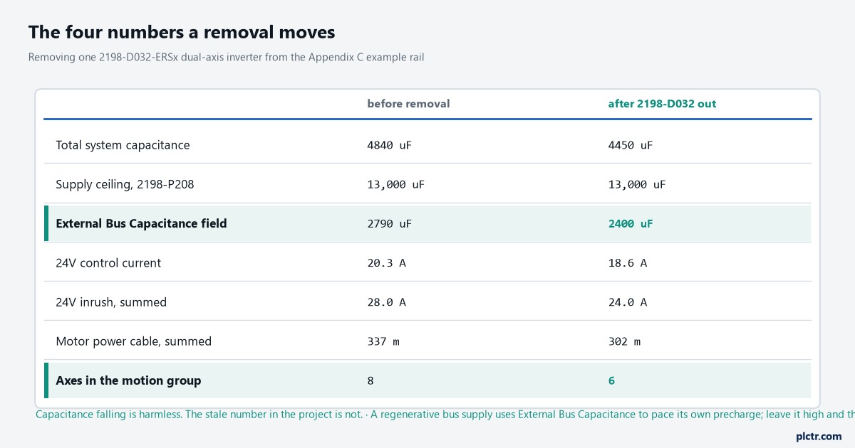
Everything except the highlighted rows gets better on its own. The highlighted rows are the two entries a human has to make.
There is one removal that makes the bus worse rather than better, and it is not an inverter. Pull a 2198-CAPMOD-2240 out to reclaim 55 mm of panel and you have taken 2240 µF of energy storage off a bus that was sized with it: the troubleshooting guidance for DC-bus voltage transients on a dynamic load change is to add a capacitor module, and an external active shunt on top of it if you are seeing nuisance overvoltage faults. A capacitor module also carries the connection point that gets the DC bus out to an extended cluster, and the extension module beside it only exists to pair with one. Remove the wrong 55 mm and a second cluster loses its supply.
What the remaining axes need afterwards
Less than people expect in the project, and more than people expect on the panel.
In software the list is short. Take the axis out of the motion group’s Axis Assignment tab if the hardware has gone, delete or inhibit the module, and recheck the External Bus Capacitance field. The Bus Sharing Group numbers on the surviving modules do not change, because they describe which bus bars a module is bolted to and those have not moved. The base update period now has headroom it did not have, which is worth noticing but not worth changing on the same day. On the panel, the gap is the whole job: the DC-bus links are moulded parts, the shared-bus connection system depends on the zero-stack tabs staying engaged from module to module, and closing a 55 mm hole means unbolting everything to one side of it, shifting it, and drilling a new hole pattern from the rule in the rail layout. The end cap has to move if what you removed was an end module. The 24V bus bars are cut to module width too.
Which is why the answer, most of the time, is that you do not take the module off the rail at all.
Leave the inverter bolted where it is, with its DC-bus links and 24V bus bars intact, and inhibit it. The bus runs through it exactly as before, the capacitance and current totals are unchanged so nothing needs retyping, the panel keeps its hole pattern, and the day the machine comes back you uninhibit and re-enable instead of rebuilding a cluster. A drive doing nothing on a rail costs 1.7 A of 24V and nobody’s afternoon. Keep the axis tags, keep the module in the tree, and mark both as out of service in the project so the next person knows it was deliberate. And if the axis is coming back with different hardware, note the drive’s static IP or DHCP setting from its Network menu before it leaves the panel, and remember that reusing the same Logix Designer application means the replacement has to be the same catalogue number.
If this is a machine change rather than a fault, the mirror of this job — what has to be set in four places when an axis goes in — is the list to read backwards.