CTU, CTD and RES: The Count That Keeps Going Past the Preset
buffer_count.ACC reads 41,206 against a preset of 500, and .DN has been true since some time on Tuesday. The line is running normally, the zone-full interlock has not released since then, and nobody can find the fault because there is not one.
A CTU does not stop at its preset.
It sets .DN when the accumulated value reaches the preset, and then it keeps counting, and .DN stays set while it does. That is not an interpretation — 1756-RM018A prints it in the worked example on the CTU page: if the input continues to go from disabled to enabled, the counter continues to increment its count and the .DN bit remains set. The only thing in the instruction set that puts the accumulator back to zero is a RES. If your program does not contain one for that counter, the number climbs until somebody downloads.
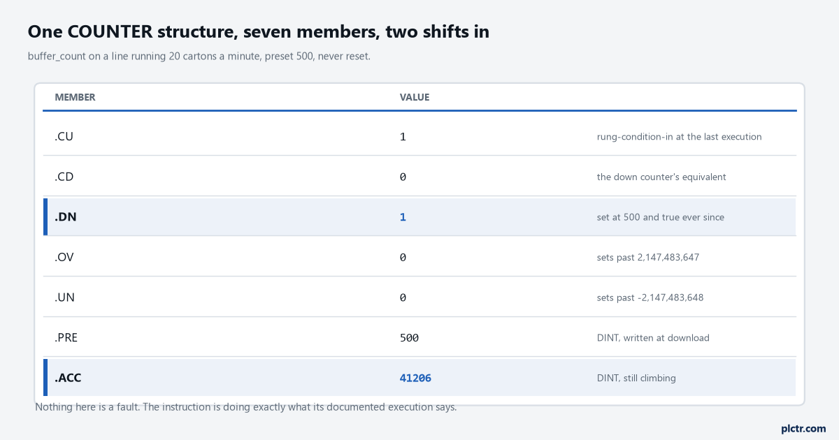
Every member here is consistent with a healthy instruction. .DN set alongside an accumulator eighty times the preset is the documented behaviour, not a symptom.
How far past the preset it will actually go
.ACC and .PRE are both DINT, and the structure carries two bits for the ends of that range.
.OV is described as the overflow bit, set when the counter increments past the upper limit of 2,147,483,647, and .UN is its mirror at -2,147,483,648. Those are not numbers you will reach by accident on a carton counter: at twenty counts a minute you have about two hundred years, and even a high-speed application taking twenty counts a second needs three and a half years of uninterrupted running to get there. The reason to know the bits exist is not the overflow. It is that RES clears them along with everything else, so .OV is a latched record rather than a live one, and a counter that overflowed at four in the morning still says so at nine — right up until the shift reset wipes the evidence.
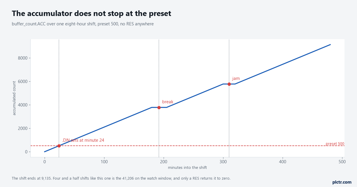
The flat sections are a break and a jam. The interesting part of this trend is that nothing happens at the preset line — the instruction crosses it and carries on with no change in slope.
What this means for the rung that uses .DN is worth being blunt about.
A zone-full interlock written as XIC on buffer_count.DN latches at 500 and never releases, because releasing requires .ACC to drop below .PRE and nothing in that program ever decrements it. The version people write instead — a GEQ comparing .ACC against a tag — behaves identically and is no better. What makes the interlock work is a CTD on the way out, so the accumulator represents what is in the zone rather than what has ever entered it, and that is exactly the pattern the manual’s own example describes: a part enters, a limit switch increments; a part leaves, another limit switch decrements; and when a hundred parts are in the buffer, .DN is true and the infeed stops.
Which bit means finished, and on which instruction
Both instructions set .DN on the same condition. Only one of them means done by it.
The CTU page describes .DN
XIC counter.DN on a down-counting job and you have built a rung that is true from the moment the batch starts and false when it ends.A down-counting batch is finished when that bit clears, not when it sets.
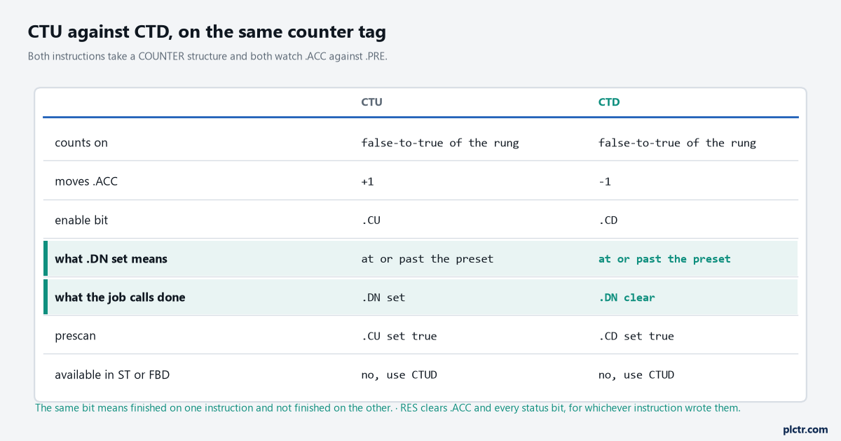
The two highlighted rows are the whole difference. Everything else about the two instructions is the same, including the structure they share.
The RES that has to exist somewhere
RES is one operand and one behaviour, and the behaviour is broader than people expect.
Pointed at a COUNTER it clears the accumulated value to 0 and the control status bits to false — .DN, .OV, .UN and the enable bit together, not just the number. Pointed at a TIMER or a TIMER_T it does the same thing to that structure, and pointed at a CONTROL it clears .POS and the status bits, which is the same instruction doing three jobs and the reason it takes a structure rather than a tag of a known type. What it cannot do is any of this in another language: RES is not available in function block and not available in structured text, which is stated in as many words on its page. The function block answer is CTUD, which carries a Reset input on the block face where a reviewer can see whether anything is wired to it, and the same argument applies to timers where RTOR’s Reset pin replaces the RES that ladder would have needed.
A counter with no RES anywhere in the project works perfectly for exactly one batch.
Two instructions, one counter, and the preset typed twice
Here is the one that survives commissioning and shows up months later.
Preset and Accum on a CTU rung are not operands in the ordinary sense; the manual calls them pseudo-operands, placeholders for members of the backing tag, and the common attributes chapter explains what they actually do: pseudo-operands are initialized when the application is downloaded and never again, unless modified by the application. Typing 500 into the Preset field writes buffer_count.PRE at download. That is the whole mechanism. And the next sentence is the trap — if you use the same backing tag in another instruction and specify a different value, the previous value is overwritten by the new value. The buffer-zone pattern puts a CTU and a CTD on one counter tag, so there are two Preset fields for one .PRE member, and if the two do not match, the download writes one of them and the reference does not say which.
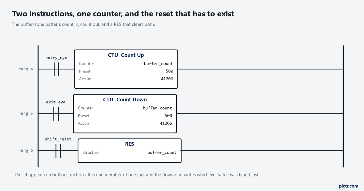
One counter tag, three rungs, and two places where 500 is typed. The number on the second instruction is not a copy of the first — it is a second writer of the same member.
There is a related version involving the HMI. An operator screen that writes buffer_count.PRE to 800 will hold 800 until the next download, at which point the pseudo-operand on the rung puts it back to 500 and the batch size silently changes overnight. Nobody connects the two events, because the download was for something else entirely and the batch size had been correct for months. If a preset is meant to be adjustable, give it its own tag, move that tag into .PRE on first scan, and leave the rung’s Preset field alone — the field then shows the value the code owns rather than a number that outranks the operator once per download.
The scan that does not count
A CTU counts when the rung goes from false to true, and it detects that edge itself using .CU.
There is no ONS required in front of it, which is the first thing people add and the first thing to remove. The consequence sits at the two extremes. A bit that stays true for eight hundred scans counts once, which is what you want. A pulse that goes true and false inside one scan of the task is never seen at all, because the instruction only ever looks at the rung when it executes, and the minimum gap arithmetic that decides whether your photo eye can be trusted is worked through in counting cartons at the end of the line. Between those two, the controller behaves exactly as documented.
The instruction only ever looks at the rung on the scan it executes.
Prescan is the other edge case and it is the friendly one.
On the transition to Run the controller sets .CU true, and the reference says why in the execution table: to prevent invalid increments during the first program scan. So a counter whose rung was already true when the controller went to Run does not record a count for the state it was already in — it waits for a genuine transition. That is the right behaviour and it is worth knowing when you are counting events that a first-scan routine also touches, because the interaction with the first scan bit and what S:FS must never do is where initialisation logic and counters usually collide.
What to check next
Search the project for the counter’s tag name and count the hits before you touch anything. A CTU with two hits — the instruction and one comparison — has no reset and is the article you are reading. Then decide out loud what the accumulator is supposed to represent: how many are in the zone right now, which needs a CTD, or how many have passed since a shift boundary, which needs a RES on that boundary and somewhere to write the total before it goes. If it is the second one, write the value to the HMI or a historian in the same rung as the RES, one-shot, in that order, because a counter that is cleared before it is read loses a shift of production data and nothing in the controller will tell you it happened. The instruction-by-instruction reference for the rest of the family is in timer and counter instructions, and the counting-for-verification pattern — where the count is evidence rather than control — is in sortation verification.