MSO, MSF and MASD on a Logix Axis: Enabling It, Dropping It, and the One That Opens the OK Contact
An MSO against a 2198-D032-ERS4 axis sets ServoActionStatus and DriveEnableStatus, and it does not set its own .DN bit in the scan that fired it. On a 2 ms coarse update period the drive answers several updates later, which on a busy machine is long enough for the rung sequenced off .EN to have started the move already.
So the short version, for anyone wiring up an enable sequence this afternoon. The MSO instruction asks the drive to close the loop and sets .DN when the drive says it has; MSF drops the same axis back to Stopped and leaves the position counting; MASD is a different animal, because it opens the module OK contact, clears every motion .IP bit on that axis and refuses every motion instruction afterwards with error 7 until an MASR resets it.
Three instructions, three different exits, and only one of them ever needs a reset.
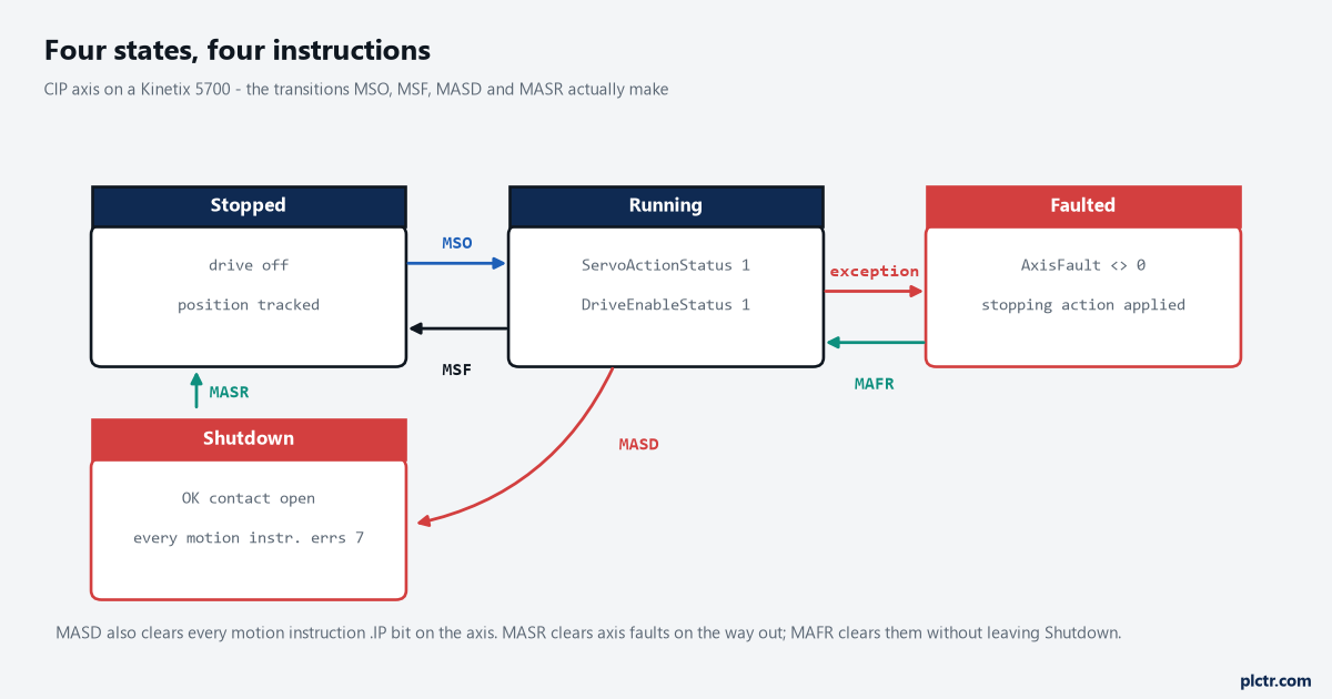
The arrow that catches people is MASD. It reaches the Shutdown box from anywhere, and the only ways out of that box are MASR, MGSR and MCSR.
What the MSO instruction actually asks for
MSO takes two operands and no more: the axis, and a MOTION_INSTRUCTION control tag. What it does with them is send a request through the motion planner to the drive, and the reference manual is direct about the cost of that — the instruction execution may take multiple scans, because it needs multiple coarse updates to complete, and .DN is set only when the request is finished. So the bit that means the drive is enabled is .DN, and behind it the two axis status bits ServoActionStatus and DriveEnableStatus. The bit that means nothing at all is .EN, which is set the moment the rung goes true and stays set until the transaction completes and the rung goes false again. MSO is also transitional. Hold the rung true with a maintained selector switch and the instruction fires once, on the edge; leave it true and toggle nothing, and a later MSF followed by the operator expecting the same switch to re-enable will do nothing at all, because there was no new false-to-true transition to fire on.
One instruction, one control tag. Share a MOTION_INSTRUCTION tag between two motion instructions and the second one errs with .ERR 3, Execution Collision, whenever the first is still busy.
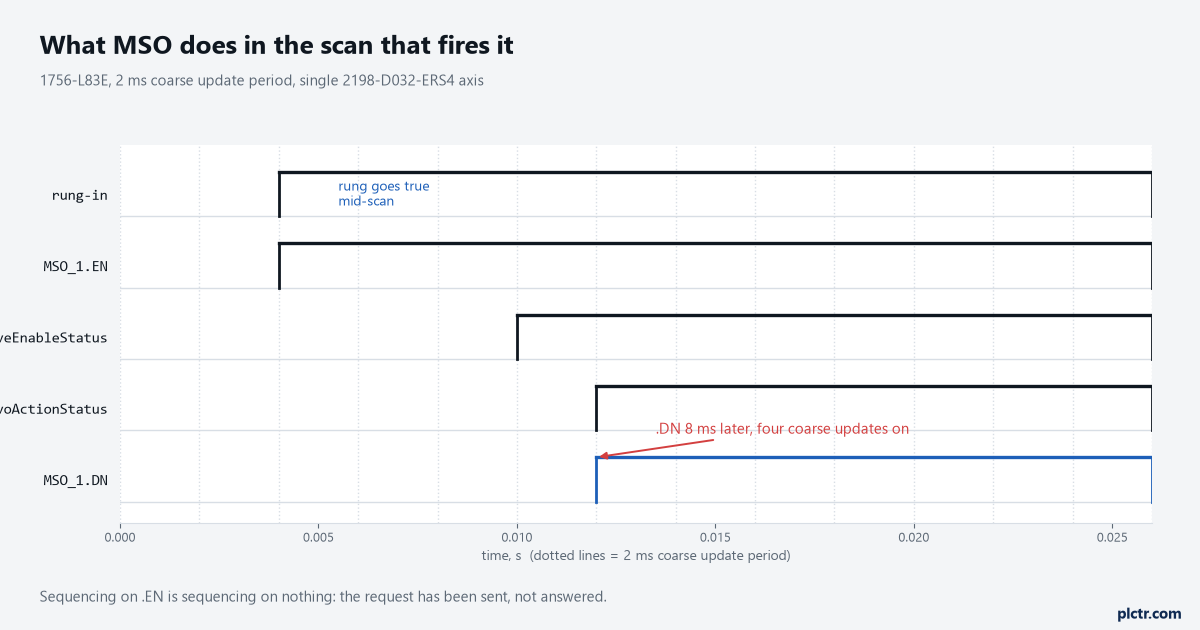
Eight milliseconds is nothing on a packaging machine and everything in a sequence step. The gap between .EN and .DN is where the request is in flight.
The errors are worth knowing by number rather than looking up, because there are only a handful you will ever see on an enable rung. .ERR 22 is Axis In Motion, and MSO throws it if the axis is already moving — the manual says plainly that MSO should not be used while the axis is moving. .ERR 7 is Shutdown State Error, and the corrective action printed next to it is the answer: execute an MASR. .ERR 11 is Axis Not Configured, which on a new machine usually means the axis exists as a tag but was never assigned to the motion group. .ERR 19 is Group Not Synchronized. .ERR 12 is Servo Message Failure, and for MSO it carries three extended codes, of which extended code 12 means the axis is shut down.
Four numbers worth memorising, and 7 is the one that says the rung will never work.
There is a second reason MSO can sit there doing nothing and never err: the axis may be in the Start Inhibited state, where a condition such as Safe Torque Off Active holds it out of Running.
That has an article of its own later in this series, because the fault-finding path is not this page.
MSF is a disable, not a stop
The MSF instruction turns the drive output off and the servo loop off, immediately, and it disables any motion planners that were active at the time. What happens to the load after that is not the controller’s decision. The manual’s wording is that the stopping behaviour varies with the type of drive: in some cases the axis coasts, in others it decelerates using the drive’s available stopping torque, and on a CIP axis the Stopping Action attribute is what selects between Disable and Coast, Current Decel and Disable, Ramped Decel and Disable, and the two Hold variants. A vertical axis with no brake and Disable and Coast configured will do exactly what that phrase says. The useful property of MSF, and the reason it is not just a weaker MASD, is that position keeps being tracked while the loop is open. Push the axis by hand, wind it off a jam, put it back roughly where it was, and the next MSO closes the loop at the new position with no re-home needed.
Position keeps counting while the loop is open, and that is the whole point of MSF.
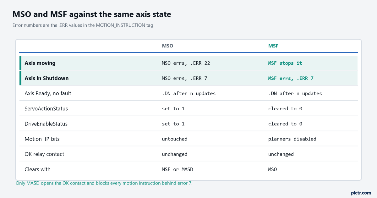
Read the middle two rows together. Both instructions err with 7 in Shutdown, which is the tell that the axis needs MASR and not another attempt at MSO.
MASD, and the contact nobody remembers is there
MASD disables the drive output, disables the servo loop, clears all motion processes in progress, clears every motion instruction .IP bit that was set for that axis, and opens the OK solid state relay contact where the module has one. That last item is the one that surprises people, and the manual gives the reason it exists: the OK contact is there to be wired into the E-stop string that controls main power to the drive system. There is typically one OK contact per motion module. On a dual-axis inverter that means an MASD aimed at one axis opens the contact that belongs to both, and MASR on that one axis may not close it again — the contact closes when no axis associated with the module is left in Shutdown, so both axes may need resetting. Meanwhile every instruction that initiates motion is blocked. An MAJ, an MAM, an MAH, even another MSO: all of them come back with error 7 until a Motion Axis Shutdown Reset, a Motion Group Shutdown Reset or a Motion Coordinate Shutdown Reset has run.
MASR clears the axis faults on its way out and leaves the axis in Axis Ready. MAFR clears faults without leaving Shutdown at all.
That difference matters when an axis is both faulted and shut down, which is the normal state after a real event. MAFR on its own takes the fault status away and changes nothing else — the manual is blunt that MAFR does not perform any other recovery, and that if the condition which caused the fault has not been fixed the axis faults again immediately. Chaining MAFR then MASR then MSO on three consecutive scans is the sequence most machines end up with, and each one of those has to wait properly.
Every step in that chain waits on the previous instruction’s .DN, never on its .EN.
The dead end: MASD is not a safety function
It looks like one. It disables the power structure, it opens a relay contact, and it needs a deliberate reset — three properties that make it read like a protective stop. It is not one. MASD is a software command that travels the same path as every other motion instruction, through the controller and the motion planner to the drive, and nothing about that path is rated for a safety function. The integrated Safe Torque Off on a Kinetix 5700 is the rated function, and it is built from hardwired or networked safety inputs that do not depend on the program scanning. Use MASD to put a machine into a state where motion cannot be commanded, by all means, and wire the OK contact into the control circuit if the design calls for it. Do not let it stand in for STO on a risk assessment, and do not let this page substitute for one either: the category and performance level your machine needs is decided by your own assessment against ISO 13849-1 or IEC 62061, and validated on the machine.
A drive that will not enable because a safety input is open is a different problem again. The idea will be familiar to anyone who has read what F059 on a PowerFlex 525 means — the drive is healthy and the enable path is not.
Which bit the next rung should sequence on
Structured text makes the pattern clearest:
IF Enable_Req AND NOT Enable_Req_Last THEN
    MSO(Axis_Infeed, MSO_Infeed);
END_IF;
Enable_Req_Last := Enable_Req;

Axis_Ready := MSO_Infeed.DN AND Axis_Infeed.ServoActionStatus
              AND NOT Axis_Infeed.AxisFault;
MSO_Infeed.DN alone is not enough, because .DN stays set after it arrives and tells you nothing about what happened since. The axis status bit does. Gate the sequence on both, add the fault word, and the step cannot advance into a drive that dropped out two seconds ago. If a shared control tag is the suspect — and .ERR 3 usually means it is — cross-referencing the tag in Studio 5000 finds every instruction holding it in about a minute.
Two instructions sharing one control tag is a bug that only shows under load.
Next thing to do: put MSO_1.EN, MSO_1.DN, ServoActionStatus and AxisFault on a controller trend at 10 ms and fire the enable once. You will see the request-to-answer gap on your own group period rather than mine, and that number is the one your sequence has to allow for. Catching it with a trend in the controller is the same technique as for any short-lived event. If the axis has not been built yet, the walkthrough from motion group to first move sets up everything this page assumes is already there.