Driving a 24 V Solenoid from a 1769-OB16: Leakage Current and the Bleeder
The 1769-OB16 specification table puts off-state leakage current at 1.0 mA maximum at 26.4V DC, and the footnote underneath tells you what to do about it: a 5.6 kΩ, 1/2 W loading resistor in parallel with your load. For a 24 V solenoid valve you will almost never need that resistor, and the arithmetic that proves it takes one line.
One milliamp through a 128 Ω coil is 0.13 V.
That number is the whole answer for a real valve, and everything below is about the cases where it is not, plus the measurement that sends people down the wrong path first. All of it is the 1769-OB16 as published in 1769-TD006H, November 2023, in a Compact I/O bank on a 1769 CompactLogix.
What 1.0 mA does to whatever is on the terminal
Leakage is a current, not a voltage, so the load decides what it turns into.
A 24 V DC pilot valve of the sort that sits on a manifold draws 4.5 W, which is 188 mA at 24 V and a coil resistance of about 128 Ω. Push the module’s worst-case 1.0 mA through 128 Ω and you develop 0.13 V across the coil, which is three orders of magnitude below anything the armature responds to, and the valve stays shut. Double the coil power and the number halves. Halve it and you get 0.26 V, still nothing. The reason this comes up at all is that the same 1.0 mA behaves completely differently when the thing on the terminal is not a coil: an electronic 24 V input with a 10 kΩ input impedance develops 10.0 V, which is inside the range a lot of 24 V devices will still read as on, and a 10 MΩ digital multimeter develops the full supply voltage because it cannot sink 1 mA at any voltage below it.
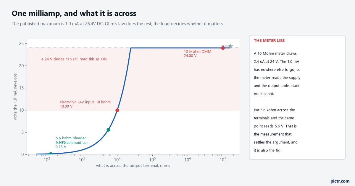
The curve is Ohm’s law and nothing else. Where your load sits on it decides whether the loading resistor is worth a terminal.
So the question is never “does the 1769-OB16 leak”. It does, by specification. The question is what the leakage is across.
The meter reading that starts the wrong job
A technician measures an off output, gets 23.8 V, and condemns the card.
This is the single most common way an afternoon disappears on a Compact I/O bank, and it is arithmetic rather than a fault. A 10 MΩ meter across a 24 V rail draws 2.4 µA; the module is prepared to push 1.0 mA, four hundred times more, so the meter never loads the point down and reads within a fraction of a volt of the supply. The output is off. The meter is right. The conclusion is wrong. Put any real load across the same terminals, or just clip a 5.6 kΩ resistor across the meter leads, and the reading collapses to 5.6 V or below, which is the proof the transistor is doing its job. Doing that once, in front of whoever is convinced the module is faulty, ends the argument faster than any amount of explaining, and it costs a resistor out of the drawer.
A meter that loads the circuit tells you the truth. One that does not tells you the leakage.
When the resistor is actually the right answer
Wire the 5.6 kΩ when the load is electronic rather than magnetic.
The cases that genuinely need it are the ones where the 1769-OB16 output is not driving a coil at all: the 24 V input of a weigh controller, a safety relay’s reset input, an electronic time delay relay, a counter, a frequency inverter’s digital input, or the input card of somebody else’s machine at the far end of a tray. All of those present tens of kilohms instead of a hundred ohms, and all of them will sit at 10 V or more on a leaking output, which is the grey band where a 24 V input is neither reliably on nor reliably off. The 5.6 kΩ value is not arbitrary either. At the worst-case 1.0 mA it caps the off-state voltage at 5.6 V, comfortably under the off threshold of anything built to IEC 61131-2, and while the output is on it burdens the point with 24 V ÷ 5600 Ω = 4.3 mA and dissipates 0.10 W, which is why the footnote specifies a 1/2 W part and not a 1/4 W one.
Fit it at the load end, not at the card. A resistor in the panel proves nothing about the 80 m of cable between.
The diode is a separate footnote, and it is not optional
Footnote 2 on the same page asks for a 1N4004 reverse-wired across the load for transistor outputs switching 24V DC inductive loads.
That is a different problem from leakage and it catches people who have already sorted the leakage out. A solenoid coil is an inductor, and when the 1769-OB16 turns it off in its published 1.0 ms the collapsing field drives the output terminal well above the supply rail until something absorbs the energy. With a diode across the coil, cathode to the positive side, that current circulates in the coil and the diode and dies away quietly. Without one it lands on the module’s output stage every single operation, and on a 1 Hz indexing valve that is 86,400 hits a shift. Outputs that fail one point at a time, months after commissioning, on the points that drive valves rather than the points that drive lamps, are usually this.
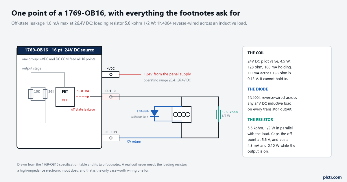
The diode and the resistor solve different problems and sit in different places. Neither one substitutes for the other.
The diode costs you turn-off time, which matters on a fast-cycling valve. A 1N4004 across a coil stretches the drop-out by tens of milliseconds because the current keeps circulating, and on a high-speed diverter that is the difference between hitting the gap and missing it. Where the timing is tight, a diode with a zener in series, or the valve manufacturer’s own suppressor block, gives you the protection without all of the delay. What you must not do is leave the coil unsuppressed because somebody once measured the drop-out and did not like it.
Four amps a module, not eight
Here is the limit that bites on a machine with a lot of valves, and it is not the one on the point.
The 1769-OB16 is rated 0.5 A per point at 60 °C and 1.0 A per point at 30 °C, which reads like a generous card until you notice the next two rows: 4.0 A per module at 60 °C and 8.0 A at 30 °C. Sixteen points at the per-point maximum is 8.0 A, so at 60 °C the module runs out of total current when exactly half its points are loaded to their individual rating. Nobody draws 0.5 A per valve, so this is not usually a wall you hit head-on. It becomes one when the panel is full of 0.25 A interposing relays: sixteen of those at once is 4.0 A on the nose, with no margin at all, and the summer ambient inside a sealed enclosure above a hot process is nearer 55 °C than the 30 °C the generous column assumes. The surge row matters too. The module will pass 2.0 A for 10 ms, repeatable every 2 seconds, and a bank of pilot lamps switched together can ask for more than that on a cold filament.

Eight points at the per-point maximum fills the module at 60 °C. The per-point figure is a ceiling for one output, not a budget you can multiply by sixteen.
Add the loading resistors into that budget while you are there. Four of them at 4.3 mA is 17 mA, which is noise, but sixteen of them is 69 mA and it is real.
The protected card does not change this decision
Somebody will suggest the 1769-OB16P, because “protected” sounds like it covers this.
It does not. The 1769-OB16P is electronically protected on the output side, which is about what happens when you short a point to common, and its published off-state leakage is identical: 1.0 mA at 26.4V DC. What the protection costs is speed and heat. Turn-on goes from 0.1 ms to 1.0 ms, turn-off from 1.0 ms to 2.0 ms, and maximum heat dissipation rises from 2.11 W to 2.69 W even though the card draws less backplane current at 5.1V, 160 mA against 200 mA. The on-state voltage drop is better on the protected card, 0.5V DC against 1.0V DC at 1 A, which is the one row where it genuinely wins.
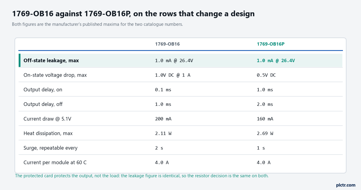
Pick the protected card for short-circuit behaviour. Pick it for leakage and you have spent money on the wrong row.
What to do at the panel
Take the coil resistance of whatever is on the terminal, in ohms, and multiply it by 0.001. If the answer is under about a volt, the leakage is irrelevant and no resistor goes in. If it is over five, fit the 5.6 kΩ at the load end. Anything in between is worth measuring under load rather than guessing, and the PLC troubleshooting method that starts by loading the circuit will get you there in a few minutes.
Then count the amps. Add up every output that can be on at once, compare it against 4.0 A rather than against sixteen times the per-point figure, and if you are inside 80% of it, split the valves across two cards before the panel is built rather than after the first hot week. The rest of the sinking and sourcing decisions on a Compact I/O bank are in the I/O module basics article, and if a point is genuinely dead rather than leaking, the Allen-Bradley I/O fault causes are the next place to look.